
Operating instructions
Dayton Operating Instructions and Parts Manual
7
Model 4E236C
Version B - For Reduction G016.J
®
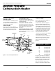
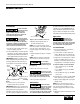
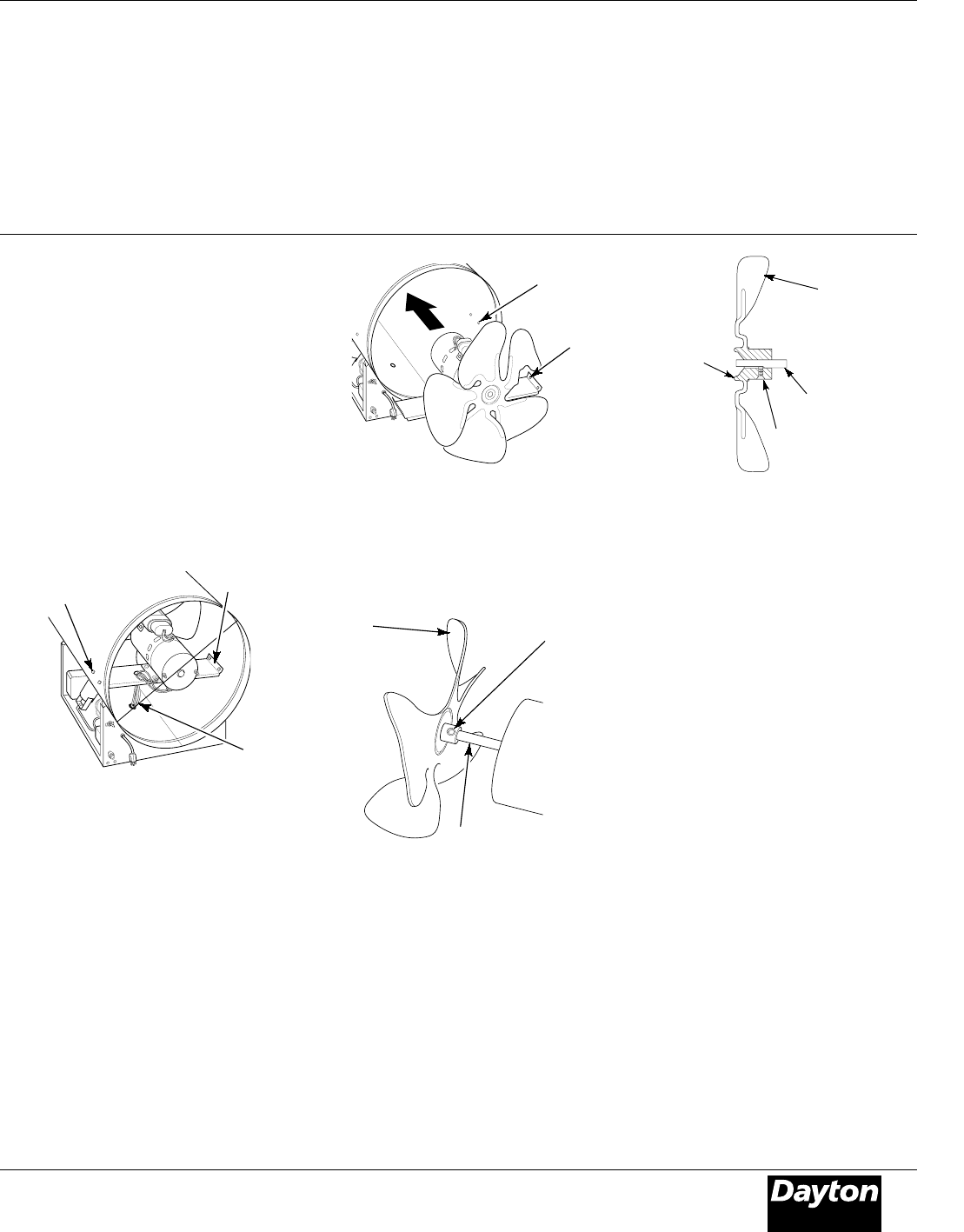
8. Turn motor and blade around and
place into shell backwards.
NOTE: Motor will go into shell first
(See Figure 8).
9. Line up rear mounting holes in
shell with first hole on each side of
motor mount (See Figure 8).
NOTE: When holes are lined up, blade
should be outside of shell.
10. Holding mounting bolt, carefully reach
through fan blades into rear of heater. Be
careful not to damage fan pitch. Insert
bolt through motor mount and shell.
With free hand, attach nut finger tight.
Repeat process for other mounting hole.
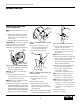
Setscrew
Motor
Shaft
Figure 9 - Fan Blade, Motor Shaft, and
Setscrew Location
Figure 8 - Fan Blade and Motor Turned
Around
First
Hole
Rear
Mounting
Hole
11. Use 1/8" hex wrench to loosen
setscrew which holds blade to
motor shaft (See Figure 9).
12. Slip blade off motor shaft.
13. Clean blade using soft cloth
moistened with kerosene or
solvent.
14. Dry blade thoroughly.
15. Replace blade on motor shaft.
Make sure setscrew is touching
back of flat surface on motor shaft
(See Figure 10).
16. Place setscrew on flat of shaft. Tighten
setscrew firmly (40-50 inch-pounds).
Figure 10 - Fan Blade Cross Section
17. Remove two nuts and bolts secur-
ing motor mount to shell.
18. Pull motor and blade from shell
then turn around. Carefully place
back in shell.
NOTE: Blade will go into shell first.
19. Line up mounting holes in shell with
holes on motor mount. Replace four
bolts through shell and motor
mount. Insert bolts from outside of
heater. Tighten nuts firmly.
20. Route motor wires through hole in
bottom of shell (See Figure 7).
21. Connect motor wires as follows
(See Figure 6, page 6):
• white wire—to terminal board.
NOTE: Attach to empty connector on
white wire side of terminal board.
• black wire—to terminal board.
NOTE: Attach to empty connector on
black wire side of terminal board.
• blue wire—to thermal switch wire
• orange wire—to solenoid valve
• green wire—to grounding screw
on shell
22. Replace side cover.
23. Replace fan guard.
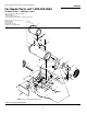
Fan
Blade
Mounting
Bolts
Motor
Wires
Motor
Mount
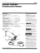
Figure 7 - Location of Fan Blade and Motor
6. Remove nuts and mounting bolts
holding motor mount to shell (See
Figure 7). Use 3/8" nut-driver and
7/16" wrench.
7. Carefully pull motor and fan out of shell.
IMPORTANT: Be careful not to damage
blade. Do not set motor and blade
down with the weight resting on
blade. This could damage blade pitch.
NOTE: Pull wires through hole one at a
time.
SERVICE PROCEDURES
Maintenance (Continued)
Fan
Blade
Motor
Shaft
Setscrew
Hub