
Operating instructions
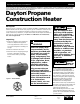
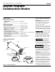
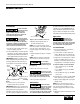
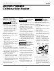
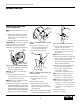

Dayton Operating Instructions and Parts Manual
9
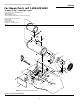
Model 4E236C
Version B - For Reduction G016.J
®
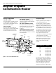
4E236C
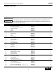
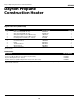
Reference Part No. For
Number Description Model 4E236C Quantity
1 Outer Shell Assembly 097844-03 1
2 Combustion Chamber Assembly 097847-01 1
3 Burner Assembly 097849-01 1
4 Ignitor 097805-01 1
5 Cleat 097918-01 2
6 Handle 097917-01 1
7 Ignitor Cable 097806-02 1
8 Fan 097811-01 1
9 Motor 097802-01 1
10 Shorty Bushing M50104-02 1
11 Fan Guard 097838-02 1
12 Strain Relief Bushing M11143-1 1
13 Cord Assembly 098219-17 1
14 Male Fitting 097809-01 1
15 Solenoid Bracket 097828-01 1
16 Solenoid Valve 098201-01 1
17 Fuel Tube 100145-01 1
18 Nozzle 099679-01 1
19 Side Cover 097833-04 1
20 Side Cover 097833-03 1
21 Thermal Switch Kit 101732-03 1
22 Motor Mount 097829-02 1
23 On/Off Switch Assembly 098226-01 1
24 Wire Assembly M9900-170 1
25 Terminal Board 099125-01 1
26 Base 100408-03 1
27 Rear Plate Assembly 097848-01 1
28 Elbow Fitting 100146-01 1
29 Compression Fitting 098827-01 1
30 Hex TPG "F" 6.32 x .25 Screw M10908- 1 2
31 Built-In Thermostat 097657-03 1
32 Thermostat Knob 104905-01 1
33 D.S.I. Control No. 2003-19 M51605-02 1
34 D.S.I. Control No. 2003-45 M51605-05 1
35 DSI Wire Harness (DSI Control 2003-45 only) 110267-01 1
Repair Parts List
Use only original repair parts. This heater must use design-specific parts. Do not substitute or use
generic parts. Improper repair parts could cause serious or fatal injuries. This will also protect your
warranty coverage for parts replaced under warranty.