
Instruction manual

REF
NO.
2
3
4
5
6
7
8
9
10
11
12
13
14
15
16
8922A
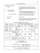
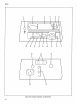
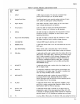
Table
2-1. Controls, Indicators,
and
Connectors (cont)
NAME
INPUT
Analog Panel
Meter
Digital Display
Annuniciators
UN
CAL
RELATIVE REFERENCE
2/20/200/700
POWER
Switch
dBm REFERENCE
REL/dBm
dB/VOLTS
STEP
UP
HOLD/AUTO
FILTER
AC/AC+
DC
(damping)
F1
FUNCTION
A
BNC
input
connector. The
low
side
is
isolated
from
power ground through a pair
of
parallel
diodes.
Uncalibrated panel
meter provides
analog
tracking
of
input
level; useful for peaking and nulling
indications.
LED
display provides a direct readout
of
the
input
signal
level; includes decimal
point
and
polarity.
LED's
that
light
to
indicate
the
selected
measurement
function
V (volts). mV (millivolts)
or
dB
(decibels).
kl
LED
that
light
to
indicate
that
the
instrument's internal
protection circuitry
is
energized, see
Crest
Factor,
under
operating instructions.
kl
LED
that
lights
to
indicate
that
the
voltmeter
is
in
the
dB
display
mode and using a relative voltage reference.
Indicate
DMM
range by decimal
point
locations.
A push-push switch used
to
turn
the
instrument
ON
(in) and
OFF
(out).
Rotary switch used
to
manually select
1-of-12 reference
impedances when
the
dBm and dB
display
modes are
selected.
A push-push switch used
to
select
either
the
relative
dB
or
the
dBm
display
mode. When REL
is
depressed,
the
existing
input
level
is
used
to
establish
a
0
dB reference.
Subsequent
level
changes
at
the
input
are
displayed
in
dB
and
referenced
to
the
operator
established 0
dB
level.
When dBm
is
selected,
measurements are
displayed
in terms
of
dBm
and
the
dBm
REFERENCE setting.
A
push-push switch used
to
select
either
the
voltage
(out)
or
dB (in)
display
mode.
A
momentary
pushbutton
switch used
to
incrementally
step
the
voltmeter
to
its higher range. This switch
is
enabled only
when
the
HOLD
RANGE
mode
is
selected.
A push-push switch used
to
select
the
manual (HOLD)
or
autorange
(AUTO)
mode.
Selecting HOLD (in)
enables
manual
upranging with
the
STEP
UP
switch.
Selecting AUTO
(out)
enables
the
unit
to
autorange.
A push-push switch which,
when
depressed, engages a
single
pole filter
to
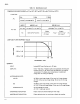
reject unwanted high frequency signals. See
the
Specifications
table
for
effect
on
accuracy.
A push-push switch used
to
include
(in)
or
delete
(out)
de
components
as
part
of
the
input
signal level.
When
AC
+ DC
is
selected
(in) damping increases which
extends
low
frequency
operation down
to
2 Hz. Reading and ranging rates are
slower.
Line fuse,
MDL
1/8A
slo-blo
..
(
5
x
20
mm, 1/SA,
slow acting for metric.)
2-3