
Instruction manual


3-8. The signal conditioner insures that the varying
levels
of
instrument input voltages are properly scaled
before being applied
to
the rms converter. The rms
converter works
on
a thermal sensing principle. Basically,
it operates
by
balancing the heating power
of
a de
feedback signal
to
the heating power
of
the ac input
signal.
When
the
two are
equal, the circuit is in
equilibrium
and
the de output voltage applied
to
the
A/
D
converter is directly representative
of
the true rms value
of
the ac input signal. The de output
of
the rms converter
is
also
applied
to
the
LINEAR
ANALOG
OUTPUT
terminals on
the
rear panel
of
the 8922A, as well as the
analog meter
on
the front panel
of
the 8922A.
3-9.
The last analog circuit
we
discuss in this section
is
the power supply. This circuit provides three regulated
power supplies (+5V,
+I5V
and -15V)
to
operate the
instrument.
3-10.
Digital
Circuitry
3-11.
The
digital circuitry comprises the
A/
D converter,
the controller,
and
the display. Together these circuits
develop a digital representation
of
the rms value
of
the
input signal, produce the commands that set the range
and function
of
the instrument, and finally display the
input value.
3-12.
The
de output
of
the rms converter is translated
to
a digital representation by the
A/
D
converter. The digital
8922A
representation
is
processed
by
the controller
to
obtain
a
bed output which
is
proportional
to
the
selected display
mode (VOLTS, dB, dBm, REL).
The
BCD
output
is
decoded
and
applied
to
the display.
3-13.
DETAILED
BLOCK
DIAGRAM
DESCRIPTION
3-14. In the following paragraphs
we
discuss, in detail,
the individual functions within
the
major
areas
of
circuitry in the 8922A. Each major circuit
area
is
detailed
in Figure 3-2. The description for each circuit
is
keyed
to
a
separate block diagram,
or
to the schematics in Section 8.
3-15.
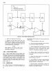
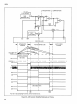
Signal
Conditioner
3-16.
The
signal
conditioner
utilizes
an
input
attenuator, two amplifiers (Amp A
and
B)
and
the
intermediate attenuator.
As
shown in
Figure
3-3, these
circuits are used to scale the varying voltage levels applied
to the instrument so
that
the input to
the
rms
converter is
always between
0.09V rms and
IV
rms.
The
diagram in
Figure 3-3, illustrates the configuration
of
the circuitry
within the signal conditioner.
The
controller,
through
a
range decoder network, issues commands which select
the
appropriate division factor in
the
attenuators
and
the
correct multiplication factor for amplifier A. Table 3-1,
lists each operating range and the corresponding division
and
multiplication factors
for
the
attenuators
and
amplifier (note
that
amplifier B has a fixed gain
ofX21).
r
UNKNOWN
I
INPUT
------------,
180
uV TO
700V
AC
INPUT
ATTENUATOR
+1.1, 110
or
11000
+
X2.6
or
26
RANGE
COMMANDS
L
____
_
FRONT
PANEL--~
STEP COMMAND
RANGE
DECODER
CONTROLLER
INTERMEDIATE
ATTENUATOR
+
1
1V
RMS
FULL
SCALE
>-----RMS
FIXED
ATX2
I
I
I
I
SIGNAL
CONDITIONER_J
-----
SENSOR
Figure 3-3. Signal Conditioner
3-3