
Instruction manual


B
Dl,
55
us
1aa
ms
INTEGRATE
'
2aa
us
DE
(REFERENCE)
INPUT/
PIN#
OUTPUT
Input
1
Input
2
Input
3
Input
4
Output
5
Output
6-1
a,
12-14
Input
11
Output
15-17
Input
18
Input
19
Output
20
Input
21
CM
1
a
0
9
a
9
0
9
a
9
OL
ONLY
CM
OL
20a-ms
EXTENDED
OVERLOAD
(OL)
AUTO
-
ZERO
1aa
ms
AUTO
ZERO
OR
AZ
1
.
8922A
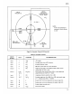
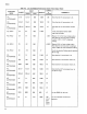
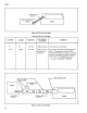
NOTE:
If
AC+
DC
(damping)
is
selected, all
times increase
by
2.5.
Figure
3-6. Controller
Timing
(A/D
Converter)
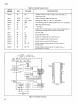
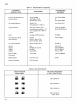
Table 3-2.
Controller
Summary
PIN
NAME
PIN DESCRIPTION
Vss
+5V
supply
CM
Compare signal
from
A/D
Converter.
CL1
External
Oscillator
input.
CL2
4aa
kHz
crystal
input
for
internal oscillator.
-
RG
Negative going pulse in the middle
of
each
strobe.
Insures
strobed data
for
DOU
is
valid.
STa-ST7
Eight strobes
that
indicate which LED
is
to
be
enabled and
accept the data on
lines
W,
X, Y
and
Z.
RD
Impedance
reference selection
line, in dB.
Fo-F
2
Encoded
range
lines,
Fa=
MSB,
F
2
=
LSB, code equals
range
#
+ 1,
voltage
swings
from;
-15
to
av.
(3
Strobe
input
on
this pin determines the lower
range
limit.
a
Strobe
input
on this pin determines the upper
range
limit.
DP
Enables display decimal point.
Voo
Ground,
OV
supply.
3-7