
Instruction manual


4-11. Cleaning
CAUTION
Do
not
use
aromatic
hydrocarbons
or
chlorinated
solvents
for
cleaning.
These
solutions will react with the plastic materials
of
the
instrument.
4-12. Clean the front panel and case with denatured
alcohol
or
a mild solution of detergent and water. Clean
-dust from the interior
of
the instrument with dry, low
pressure air
(20
psi). Contaminants can
be
washed from
the circuit board with demineralized water and a soft
brush (avoid getting excessive amounts of water on the
switches).
4-13. Fuse Replacement
4-14. The 8922A has one replaceable fuse located on the
rear panel which may be replaced with a l / 8 amp,
slo-bl~
fuse (Metric uses 5x20 mm, l / 8 amp slow acting).
4-15. PERFORMANCE TEST
NOTE
In the following procedures the instrument
(8922A) which
is
being either checked or
calibrated
is
referred to
as
the UUT (Unit
Under Test).
4-16.
The
following
paragraphs
comprise
a
performance verification test which compares the
instrument's performance to the specifications given in
8922A
Section 1 of this manual. The test
is
recommended as
an
acceptance test when the instrument
is
first received
and
later
as
a calibration procedure to verify instrument
accuracy at the scheduled calibration periods (90-days).
It
can also
be
used as an aid
in
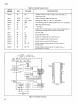
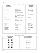
troubleshooting. Test
equipment required for the performance test
is
listed in
Table
4-1.
If
the recommended test equipment
is
not
available, equivalent test equipment may be substituted.
To insure optimum results, the test must be performed
at
an
ambient temperature between
18
and
28
degrees
Celsius with a relative humidity
of
80%. Allow the
instrument to warmup
at
least
30
minutes, with the case
cover in place, before attempting the performance test.
4-17.
If
the instrument fails
to
meeet
the
performance
test limits, calibration adjustment,
troubleshooting,
and/
or
repairs are indicated. Procedures for calibration
adjustments and troubleshooting are given later in this
section
of
this manual.
NOTE
In all
of
the
procedures in this section,
precautions should be taken to minimize
ground currents, stray fields, etc.
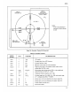
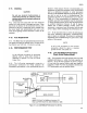
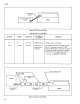
4-18. Low and Midband Performance
Check (Volts Display Mode}
4-19. This procedure will verify
tha~
the UUT's low
and
midband performance
is
within the limits specified in
Section
I.
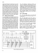
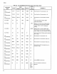
Set up the test equipment
as
shown in Figure
4-1, and select the required function and input signal as
indicated
in
Table 4-3. Note any deviation between the
UUT performance and the specified limits.
LINEAR
ANALOG
OUTPUT
8922A (REAR)
SHIELDED
CABLE
POWER
AMP
(5205)
\
8922A (FRONT)
NOTE:
WHEN
TESTING THE 8922A A BANANA
TO
BNC
ADAPTER MUST
BE
USED
(POMONA 1296)
Figure
4-1.
Low
and Midband Performance Test Set-Up
DVM
(8600A)
4-3