
Instruction manual

8922A
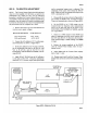
603-17. TROUBLESHOOTING obtained then the performance test and calibration
procedure must be repeated.
603-18.
Table
603-4
should be completed ONLY
if
the
performance test and calibration procedure indicate the
the
-003
Counter
Output
Option IS NOT operating
correctly.
This
table
includes
voltage
levels
and
waveforms
of
a properly functioning-003 Option.
If
you
are unable to obtain any value (±15%) then you should
replace the defective component and repeat the entire
troubleshooting procedure. However, if all values are
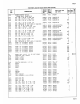
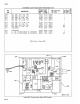
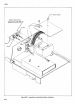
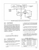
603-19. LIST OF REPLACEABLE PARTS
603-20. A list
of
replaceable
parts
for the Counter
Output Option
is
given in Table 603-5 and shown in
Figure
603-6.
Refer to Section 5
of
this manual for
ordering information.
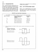
603-6
Table 603-4. Counter
Output
Option Troubleshooting
1. Using the
8020A
or
any compatible 3 1
/2
digit
meter, measure the
following
supply voltages.
SUPPLY
VOLTAGE
MEASURE BETWEEN
HIGH
DVM
DISPLAY
TERMINAL
AND
LOW
(8020A)
TERMINAL
+15 U401·1
and
Input
Common~·
+15.00, ±0.1 v
-15
U401-6
and
Input
Common
*
-15.00
±0.2V
+5
T402-2
and
Input
Common
*
+5.00
±0.25V
+5.3
U401-1
and
Chassis
Ground*
+5.3
±0.3V
-6.5
U401-6
and
Chassis
Ground*
-6.5±0.3V
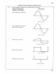
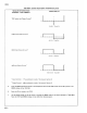
2.
Using
an
oscilloscope
(with
x10 probe) Tek
475
or equivalent, check the
following
points
for
the indicated
waveforms.
MEASURE BETWEEN HIGH
TERMINAL-
LOW
TERMINAL
T402-1 and
Input
Common*
T402-3 and
Input
Common*
T402-6 and
Input
Common*
T402-8 and
Input
Common*
SCOPE
DISPLAY
0
-+----1-+-li..t---"'1!---+--+-b+-t--+-
2V/DIV-10
µs/DIV
0
-+--l,...._+-+-+---+---l-+--+-+-+---
2V/DIV
-10µs/DIV