
User Manual


3
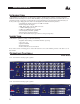
Input Gain Control: Thiscontrolsetsthesignalleveltotheequalizer.Itiscapableof-12dBto+12dBofgain.Its
effectisapparentbyviewingtheOUTPUTLEVELBARGRAPH.
EQ Bypass: Thisswitchremovesthegraphicequalizersectionfromthesignalpath.(SeeBlockdiagramonPage
8.)TheBYPASSswitchdoesnot,however,affecttheINPUTGAIN,orLOWCUTfilters.
EQ Bypass LED:ThisredLEDlightswhentheEQisinbypassmode.Notethatbypassmodeonlyeffectsthe
graphic equalizer section of the 12 Series EQs. TheINPUTGAIN and and LOWCUT controls remain unaffected
when the EQ is bypassed.
Boost/Cut Range Selection Switch and LEDs: Thisswitchselectswhichofthetwoboost/cutrangestheequalizer
willuse,either±6dBor±15dB.TheredLEDlightswhenthe±15dBrangeisselected,andtheyellowLEDlights
whenthe±6dBrangeisselected.NotethattheBOOST/CUTswitchisslightlyrecessed.Thisistopreventacciden-
talactivationoftheswitch,possiblycausingdamagetoothersoundsystemcomponents.
Output Level Bar Graph: ThesefourLEDsindicateoutputleveloftheequalizer.TheredLEDis3dBbelowclip-
pingandismarkedas+18dBu.Itmonitorsthelevelattheoutputoftheequalizerafterallotherprocessing.
Clip LED: ThisLEDlightswheneveranyinternalsignallevelreaches3dBbelowclippingwhichmayoccurwhen
anyofthefollowinghappen:1)theinputsignalis“hotter”than+22dBu,2)excessivegainisappliedbytheinput
gaincontrol,or3)excessiveboostisappliedusingthefrequencysliders.
Frequency Band Slider Controls: Each one of these slider potentiometers will boost or cut at its noted frequency
by±6dBor±15dB,dependinguponthepositionoftheBOOST/CUTRANGEswitch.Whenalltheslidersarein
the center detented position the output of the equalizer is flat. The frequency band centers of the 1231 are marked at
1/3rdofanoctaveintervalsonISOstandardspacings,whilethefrequencybandcentersofthe1215aremarkedat
2/3rdsofanoctaveintervalsonISOstandardspacings.
Low Cut Enable Switch: TheLOW-CUTswitchinsertsorremovesthe18dB/octave40HzBessellow-cutfilter
fromthesignalpath.WhentheLOW-CUTswitchispushedin,theLOW-CUTfilterisINtheaudiopath.
ConneCtIng the eQ to your systeM
The 12 Series Equalizers have balanced inputs and outputs that can be used with any balanced or unbalanced line-
leveldevice.Formorespecificinformationaboutcablingpossibilities,pleaserefertothesectionentitled
Installation Considerations, Page 5.
To connect the equalizer to your sound system refer to the following steps:
Install the EQs in a rack with the rack screws provided. It can be mounted above or below anything that does
notgenerateexcessiveheat.Ambienttemperaturesshouldnotexceed113°F(45°C)whenequipmentisinuse.
Althoughtheunit’schassisisshieldedagainstradiofrequencyandelectromagneticinterference,extremely
highfieldsofRFandEMIshouldbeavoided.
All three types of connectors for the inputs and outputs can be used for balanced or unbalanced connections.
Theuseofmorethanoneconnectoratatimefortheinputscouldunbalancebalancedlines,causephasecancel-
lation,shortaconductortoground,orcausedamagetootherequipmentconnectedtotheequalizer.Morethan
oneoutputmaybeusedsimultaneouslyaslongasthecombinedparallelloadisgreaterthan600Ω.
switch
Note: Be sure to reduce audio levels at the power amplifiers when changing the setting of this switch as it may generate an audible transient.
ConnecttheACpowercordtotheACpowerreceptacleonthebackoftheequalizer.RoutetheACpowercord
to a convenient power outlet away from audio lines. The unit may be turned on and off from the rear panel
OPERATION MANUAL
12 SERIES GRAPHIC EQUALIZERS