® Owner’s Manual
® Warranty 1. Please register your product online at dbxpro.com. Proof-of-purchase is considered to be the responsibility of the consumer. A copy of the original purchase receipt must be provided for any warranty service. 2. dbx warrants this product, when purchased new from an authorized U.S. dbx dealer and used solely within the U.S., to be free from defects in materials and workmanship under normal use and service. This warranty is valid to the original purchaser only and is non-transferable. 3.
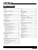
® Table of Contents Overview ����������������������������������������������������������������������� 2 Introduction ������������������������������������������������������������������������������������������������� 2 Features ������������������������������������������������������������������������������������������������������� 3 Limiter ��������������������������������������������������������������������������������������������������������43 RTA �����������������������������������������������������������
® Overview Introduction The DriveRack® PA2 represents the next generation of PA loudspeaker management processing from dbx®. With dynamics, EQ, feedback suppression, crossover, subharmonic synthesis, and delay processing, the DriveRack PA2 provides all the processing you need between your mixer and amplifiers to optimize and protect your loudspeakers.
® Features • 24-Bit A/D & D/A Converters • 48 kHz/32-Bit Floating Point Processing • dbx Type IV™ Conversion • Setup Wizard For Easy System Configuration • Level Assist For System Level Balancing • AutoEQ™ For Fast & Accurate Room Equalization Using 8-Band Parametric EQ • AFS™ For Ringing Out The System & On-The-Fly Feedback Suppression • 31-Band Graphic EQ For Tailoring The System’s Frequency Response To Taste • Subharmonic Synthesizer • dbx® Compression • Pre-Crossover Delay For Aligning The Sound System
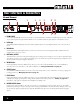
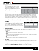
® User Interface & Connectors Front Panel 1 2 1. RTA MIC INPUT 3 5 4 6 8 7 10 12 9 11 13 Connect the dbx RTA-M measurement microphone (sold separately) to this balanced XLR input jack for easy calibration of your sound system using the built-in Wizards or for use with the RTA. This jack supplies +15V phantom power. 2. LCD Display This LED-backlit LCD display provides the visual feedback required for operating the PA2 processor from the front panel. 3.
® 9. INPUT Meters These 6-segment LED meters display the input signal level strength and available headroom, and range from SIG (signal present) to 0 (dBFS). These meters monitor the signal level right after the A/D converter and will light when the signal level is greater than or equal to the values shown in the table to the right. Input LEDs dBFS (switch set to +4 dBu) (switch set to -10 dBV) 0 -0.1 19.9 dBu 7.7 dBV 3 -3 17 dBu 4.8 dBV 10 -10 10 dBu -2.2 dBV 15 -15 5 dBu -7.
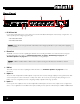
® Rear Panel 1 4 120V 5 50/60Hz 2 3 6 1. IEC AC Power Inlet Connect the included IEC power cord to this power inlet. The DriveRack PA2 ships from the factory configured for one of two specified power voltage ranges, they are: • 100-120V, 50Hz/60Hz • 220-240V, 50Hz/60Hz NOTE: Ensure the screening under this outlet matches the voltage specification in your country before applying power to the PA2. 2.
® 6. Input Switches These switches are recessed to prevent accidental switching. You may need to use the tip of your fingernail or an object with a pointy tip, such as a pen, to activate these switches. • +4dBu/-10dBv Switch This switch sets the PA2’s input sensitivity. Select the +4dBu option (switch out) when connecting a mixer or device which has a nominal output operating level of around +4dBu.
® Installing The DriveRack PA2 Installation Recommendations FOR RACK MOUNT USE ONLY. Install the PA2 in your 19” rack with the provided rack screws. When installed in a rack, make sure there is proper ventilation. The sides and back of the device should be free of any obstruction that would prevent airflow. The PA2 should not be mounted above or below anything that generates excessive heat. Ambient temperatures should not exceed 950 F (350 C) when equipment is in use.
® Network Connections Wired Ethernet Switch 1. Download and install the free DriveRack PA2 control app on the iTunes Store , Google Play™, or from www.dbxpro. com. DriveRack PA2 ® 120V 50/60Hz 120V 2. Connect a straight-through CAT5, CAT5e, or CAT6 Ethernet Switch With DHCP Enabled Ethernet cable (sold separately) to the Ethernet port on the DriveRack PA2. 3. Connect the other end of the Ethernet cable to one of the LAN ports on a DHCP-enabled network router or switch. 4.
® Applying Power 1. Ensure your power amplifiers or powered speakers are turned off. 2. Make sure the included IEC power cable provided with your PA2 has the proper connector for connection to your AC power outlet and that the power screening under the IEC power inlet on the back panel of the PA2 matches your country’s voltage requirements. 3. Connect the power cable to the AC power inlet on the PA2’s back panel. 4. Apply power to the PA2 by connecting the other end to an available AC power outlet.
® Getting Started Menu Navigation Overview The DriveRack PA2’s user interface was carefully designed to provide logical navigation and avoid deeply nested menus. The menu navigation is laid out as shown in the below diagram.
® Operating Modes Explained This section describes the different operating modes available in the DriveRack PA2 and how to enter each mode. Home Mode This is the default operating mode. It is the mode the DriveRack PA2 enters when it initially boots and is the mode which displays the selected home screen. From any menu, you can get back to Home mode by repeatedly pressing the BACK button.
® The Home Screens The home screen is the first screen which appears in the LCD display after the DriveRack PA2 fully initializes (this is also referred to as “Home mode”). There are four home screens to choose from, providing the instant visual feedback you need, when you need it. All home screens will display the currently loaded preset number and name, so you always know which preset is currently loaded. To toggle between Home screens, simply press the DATA WHEEL from Home mode.
® Configuring The DriveRack PA2 This section of the manual describes how to configure the DriveRack PA2 for your application. The easiest way to configure the PA2 is to use the built-in Wizards. However, for the veteran sound engineers and DriveRack power users, the PA2 can also be configured and tweaked manually. For example, you can create the basic configuration using the Setup Wizard, or load an existing preset, then tweak the parameters as necessary from there.
® RUN AutoEQ/LEVEL ASSIST The Level Assist and AutoEQ mic position 1 measurements should be taken with the microphone placed equidistant from the speakers, so that the three components form an equilateral triangle, as shown in the Level Assist/AutoEQ Mic Position 1 diagram.
® WIZARD OPTIONS The available options in this menu are: • AutoEQ TARGET [RECOMMENDED PA CURVE, FLAT, REFLECTIVE ROOM] When a sound system’s frequency response is flattened, it can sound a bit thin on the bottom end. The AutoEQ TARGET option makes up for this by adding a bass boost. Select the RECOMMENDED PA CURVE option (this is the default setting) to allow AutoEQ to automatically enhance the low end. Select the FLAT option if you want the system to be tuned flat when running the AutoEQ Wizard.
® About Speaker & Amplifier Tunings The PA2 has a Setup Wizard to help you configure your sound system. When you run the Setup Wizard, it will ask you to select the make and model of your speakers and amplifiers from a list of available options, referred to as “tunings”. There are speaker tunings and amplifier tunings. When you select your speakers from the tuning list, the PA2 will automatically configure the crossover, output PEQs, polarity, and in some cases, driver alignment delays.
® Manual System Optimization Tips TIP: You may want to disable the TIME OUT feature located in the Utility menu before performing any of the following system optimization procedures. This will ensure the PA2 does not revert back to the home screen throughout the process. See ‘Utility’ on page 46 for more information on disabling this feature. 1.
® The PA2’s output POLARITY parameter (located in the crossover) is used to match polarity between drivers. Some multi-way main speakers will require certain drivers to be polarity inverted when operating in bi-amped mode (bypassing the internal passive crossover network). When selecting any bi-ampable main speaker from the PA2’s speaker tuning list in the Setup Wizard, such polarity inversion will be performed for you automatically.
® your system to its fullest potential and could potentially cause damage to your loudspeakers. When you select your amplifiers in the Setup Wizard, the PA2 will automatically set the limiter thresholds and gain structure between the PA2 and amplifiers. If your amplifiers are not available in the Setup Wizard, you should choose the NOT LISTED option.
® To calibrate the system’s gain structure and PA2 limiters: WARNING! Although it is highly unlikely that you are using tube amplifiers, since they are not practical for live sound reinforcement use, please note that some tube amplifiers can be damaged if operated without a load (the speaker) connected. Therefore, do not perform the following procedure if using tube amplifiers unless you have verified they can be operated without a load connected.
® of the speaker. If the sound system is too loud when the mixer’s main faders are set to unity, this indicates that you have more power than is required for the venue and you can simply turn down your mixer’s main output faders until the desired performance level is achieved. 4. Balance The System’s Frequency Response It’s now time to balance the system’s overall frequency response by fine-tuning the amplifier attenuators.
® 6. Ring Out The System With AFS Ringing out the sound system for feedback before use allows you to squeeze a little more gain out of the system before the onset of feedback and can help ensure you’re not right at the edge of feedback during the performance. The AFS Wizard does a great job of taking the guesswork out of ringing out the sound system for feedback. However, if you prefer to ring out the system manually, you can.
® Operating The DriveRack PA2 This section of the manual describes how to operate the DriveRack PA2 after you have initially configured and optimized the system using the Wizards. This includes editing parameters and managing presets. Editing Parameters To edit a processing module’s parameters: 1. Press the module’s button (e.g., GEQ, AFS, SUB, etc.). 2. Some menus will offer a list, depending upon the currently loaded configuration, where you can select which module you want to edit.
® Managing Presets The DriveRack PA2 has two types of presets: user and factory. The user presets occupy preset memory locations1–75. The factory presets occupy preset memory locations 76–100. The difference between these preset types is that factory presets are meant to be used as templates and cannot be overwritten and user presets can be overwritten and are designed to store your custom presets.
® Storing Presets When you are satisfied with the changes made to a factory or user preset, you can store the changes to a user preset memory location. The STORE button is used to store modifications made to a preset. To store a preset: 1. Press the STORE button. You are now in Preset Store mode. 2. The current name of the preset will be shown in the LCD display and you now have the option to keep the name or rename the preset. If you do not wish to rename the preset, proceed to step 3.
® The PA2 Processing Modules & Parameters This section of the manual provides descriptions of all the processing modules available in the DriveRack PA2 and their associated parameters. Graphic EQ (GEQ) The 31-band GEQ module lets you manually tune the sound system’s frequency response and is meant to be used alone or alongside the AutoEQ PEQ (which is set when you run the AutoEQ Wizard). In previous DriveRack models, the GEQ was set when you ran the AutoEQ Wizard.
® • MYBAND This option is optimized for live music performance using a portable PA system in small to medium sized venues (coffee shops, clubs, etc.). It offers some low-end boost along with low-mid cut, which enhances the low end while preventing the system from sounding too muddy. The high end is also slightly attenuated. • SPEECH This option is optimized to enhance speech intelligibility.
® Parametric EQ (AutoEQ, HIGH, MID, LOW PEQ) There are two types of PEQs available in the PA2: the AutoEQ PEQ and the output PEQs (labeled LOW, MID, and HIGH). The AutoEQ PEQ is an 8-band parametric EQ which resides in the input processing side of the PA2 (pre crossover) and is automatically adjusted by the built-in AutoEQ Wizard. In most cases you will likely just look at the settings in the AutoEQ PEQ to see how the system was equalized after running the AutoEQ Wizard.
® • BAND(1–8) FREQUENCY [20 Hz – 20 kHz] This parameter adjusts the center/cutoff frequency of the selected EQ band. • BAND(1–8) GAIN [-12 dB – +12 dB] This parameter adjusts the gain of the selected EQ band. • BAND(1–8) Q [0.1 – 15.909] This parameter is only available with BELL type filters and adjusts the width of the selected PEQ filter. Lower Q settings provide wider filters, affecting a wider range of frequencies when adjusted.
® Advanced Feedback Suppression (AFS) Feedback is caused when an in-phase audio loop is created between an input transducer (such as a guitar pickup or microphone) and an output transducer (a loudspeaker). The DriveRack PA2 includes the exclusive AFS™ (Advanced Feedback Suppression) algorithm to help combat this dreadful phenomenon. The AFS algorithm in the PA2 is a little different than the AFS algorithm used in any previous dbx products.
® TIP: AFS works best when the signal entering the PA2’s inputs is sufficient. This requires proper gain staging between the mixer and PA2. If the signal level is too low, AFS may be slow to respond to feedback. See ‘Manual System Optimization Tips’ on page 18 for further information on gain structure and ringing out the system with AFS. NOTE: Signals sent to the PA2’s LEFT and RIGHT inputs are summed to mono before entering AFS for analysis.
® begin to round robin – meaning that if all Live filters have been set and new feedback occurs, the first Live filter set will be released then re-set at the new feedback frequency location. The Live filters can be set to release after a period of time by enabling the LIVE LIFT option and adjusting the LIFT AFTER parameter. Note that when you run the AFS Wizard, AFS will automatically switch between Fixed and Live mode operation behind the scenes.
® TIP: Since it’s not really possible to predict exactly how many Fixed filters you may need, a good setting to start with is the default setting of 6. If after ringing out the system, you feel you need to squeeze a little more gain out of the system before feedback, you can increase the FIXED FILTERS setting and run the AFS Wizard again or manually ring out only the newly added Fixed filters in the AFS menu.
® Subharmonic Synthesis (SUB) dbx’s subharmonic synthesis (or sub-synth) processing has been specifically optimized to enhance the low frequencies in audio material and was designed for use in a variety of professional audio applications, including nightclub and dance DJ mixing, theatre and film sound, sound design, music recording, live music performance, and broadcasting.
® NOTE: If you experience low-frequency artifacts on a voice when using subharmonic synthesis, try engaging a high-pass filter, using EQ, or a combination thereof on the vocal’s mixer channel to reduce the artifacts. If a high-pass filter and EQ are not enough, try lowering the overall amount of Subharmonic Synthesis applied to the signal by adjusting the SUBHARMONICS parameter. NOTE: The left and right input signals are summed to mono before the subharmonic synthesizer processes the audio.
® Compressor (COMP) A compressor is used to compress the dynamic range of the audio signal, bringing up the lower-level portions of the signal and restricting the higher-level portions of the signal. In live sound applications, it is common to compress the audio at different stages in the signal chain. For example, you may apply compression to individual instruments using the mixer’s insert points and/or a group of instruments using the mixer’s bus or group inserts.
® a 2:1 ratio would allow the output signal level to increase by only 1 dB for every 2 dB of level increase over threshold. In other words, 1 dB of compression will be applied for every 2 dB increase in level above threshold. For light compression, choose a lower ratio. For heavy compression increase the ratio. A ratio setting of about 10:1 or higher essentially turns the compressor into a limiter. Typically, a setting of 1.
® Delay There are two different delay module types available in the PA2: the input (also known as pre or backline) delay module and the output (also known as driver alignment) delay module. The output delay modules (labelled HIGH, MID, and LOW) are used to time align loudspeaker drivers which require it. Typically, driver alignment delay is only required when configuring a bi-amplified (2-way) or tri-amplified (3-way) system.
® also see a LOW OUTPUT DELAY. If you’ve configured a 3-way system, you will see an additional MID OUTPUT DELAY. Turn and press the DATA wheel to select the desired delay module. Turn the DATA wheel to scroll through the list of parameters. Press the DATA wheel to edit a selection. When in a Delay menu, pressing and holding the DELAY button for approximately 2 seconds will advance to the next delay module, wrapping around through the available modules.
® Crossover (XOVER) A crossover is used to divide the broadband signal into separate frequency bands. This allows each loudspeaker or driver in a sound system to be operated within its optimal frequency range. Using an active crossover, like that in the PA2, has the additional benefits of increasing the efficiency of your power amplifiers, lowering intermodulation distortion, and in some cases, improving the drivers’ transient response.
® dB increase in level will be created at the crossover frequency. LR stands for Linkwitz-Riley. When two Linkwitz-Riley filters are summed, there is no increase in level around the crossover frequency, which makes these type of filters very popular. The numbers next to each option represent the filter slope rate in decibels per octave. • POLARITY [NORMAL, INVERTED] Inverts the polarity of the selected PA2 outputs. Polarity inversion is used to match driver polarity in systems which require it.
® Limiter Limiters are used to set a ceiling on the signal level, preventing the signal from exceeding a predetermined threshold. For this reason, they are used to prevent the overdriving of equipment. Limiters are compressors with high ratios (typically, a ratio of around 10:1 or higher). The ratio controls in the PA2 limiter modules are fixed at infinity:1.
® • THRESHOLD [-60 dB to 0 dB] This parameter sets the level at which the limiter will begin limiting the signal. The limiter’s Threshold Indicators (shown to the right) indicate when signal is below threshold, above threshold, or in the OverEasy region. For example, if the threshold parameter is set to -17 dB, any signal which exceeds -17 dBFS will be limited, while any signal lower than -17 dBFS will be left alone. You will want to set the threshold to a setting just below the clip point of the amp.
® RTA The 31-band RTA (Real-Time Analyzer) module allows you to monitor frequency levels. This information can help with identifying system issues – such as improperly set crossover settings, blown drivers, or driver/speaker dependent level issues. It can also be used when manually tuning the sound system. RTA Parameters The RTA menu can be accessed by pressing the RTA button. Turn the DATA wheel to scroll through the list of parameters. Press the DATA wheel to edit a selection.
® Utility The Utility menu allows you to edit global system parameters and provides system information. Utility Parameters The Utility menu is accessed by pressing the UTILITY button. Turn the DATA wheel to scroll through the list of parameters. Press the DATA wheel to edit a selection. • SYSTEM INFO Selecting this option displays important PA2 system information, such as the currently installed firmware version, network IP address, and Mac address.
® Power-Up Functions Power-up functions allow you to reset DriveRack PA2 presets and settings, lock out the front-panel controls, and configure the PA2 to always power up with the output mutes enabled. These power-up functions are accessed by pressing and holding certain buttons upon power-up. The following section describes the power-up functions available in the PA2 and how to use them. Initialize With Mutes On This power-up function forces the PA2 to boot up with all outputs initially muted.
® System Lockout This power-up function locks out the PA2’s front-panel controls to prevent unauthorized tampering. The following options are available: • System Unlocked This is the default setting and allows access to all PA2 functions from the front-panel controls. • System Locked When this option is selected, all front-panel controls will be locked and a “LOCKED” message will appear in the LCD display whenever any button is pressed or the DATA wheel is turned.
® Factory Reset The Factory Reset function resets all user presets and Utility settings in the PA2 back to their factory default state. WARNING! Performing the Factory Reset procedure will permanently reset all user presets and set all PA2 settings back to their factory default state. This operation is irreversible. To perform a Factory Reset: 1. Power down the DriveRack PA2. 2. Press and hold the STORE button then apply power to the DriveRack PA2.
® Application Guide This section of the manual shows the various ways in which the DriveRack PA2 can be configured and provides system diagrams and application notes for each application type. Use these diagrams and notes for reference when initially connecting and configuring the DriveRack PA2 for your application. Full Range Application 1 (Standard) This application is suited for full range systems which do not require an active crossover.
® Full Range Application 2 (Sub-Satellite System) The full range application may also be used for some 2-way powered sub-satellite speaker systems, where you have a pair of powered mains and one or two powered subwoofers which are part of the same product series and are meant to be integrated together. These type of integrated powered speaker systems are designed by the manufacturer to be easy to setup and use.
® Full Range Application 3 (All Outputs Full Range) Some full range systems may require more than two full range outputs from the PA2. The PA2 can accommodate these systems as well, but such systems are atypical and cannot be properly configured using the PA2’s Setup Wizard alone.
® 2-Way Application This application is suited for systems using full range main speakers along with subs or for systems using bi-ampable main speakers with no subs.
® 3-Way Application This application is suited for systems using bi-ampable main speakers along with subs. In this type of application, the PA2 will split the signal into three frequency bands and send all the low frequencies out the LOW outputs to the subs, all the mid frequencies out the MID outputs to the woofers in the mains, and all the high frequencies out the HIGH outputs to the high frequency drivers in the mains.
® Preset List User Preset # Factory Preset # Name Description 1, 26, 51 76 ST.Full Range Stereo Full Range 2, 27, 52 77 M.FullRange Mono Full Range 3, 28, 53 78 ST.2WaywST.Sub Stereo 2-Way with Stereo Subs 4, 29, 54 79 ST.2WaywM.Sub Stereo 2-Way with Mono Sub 5, 30, 55 80 M.2WaywST.Sub Mono 2-Way with Stereo Subs 6, 31, 56 81 M.2WaywM.Sub Mono 2-Way with Mono Sub 7, 32, 57 82 ST.3WaywST.Sub Stereo 3-Way with Stereo Subs 8, 33, 58 83 ST.3WaywM.
® DriveRack PA2 Control Application The DriveRack PA2 control application is available for Android™, iOS®, Mac®, and Windows® compatible devices. This application is available for free and can be downloaded on the iTunes Store®, Google Play™, or from www.dbxpro.com.
® Networking Networking Overview The PA2 can be network controlled with the use of a network switch or router which has a built-in DHCP server. DHCP (Dynamic Host Configuration Protocol) is a protocol for automatically assigning IP addresses to devices on a network. The DHCP server is required to assign an IP address to the DriveRack PA2. NOTE: The DriveRack PA2 does not support control via a proxy or VPN connection.
® 3. Ethernet LED Indicators Ensure the yellow and green LEDs are lighting on the PA2’s Ethernet port (the green LED may flash which is fine). If using a wired connection from a computer, ensure that these LED indicators are also lighting on your computer’s Ethernet port. If any of these LEDs are not lighting, try removing and reconnecting each Ethernet connection.
® Technical Information Firmware Updates The USB or Ethernet connector on the back panel of the PA2 can be used to perform firmware updates. Connect the USB port to a Windows® PC for performing firmware updates using the PA2 Firmware Update Utility application. As firmware updates becomes available, the Firmware Update Utility application will be available on the PA2 product page at dbxpro.com.
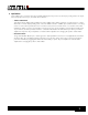
® Mute Right Low Output Left Low Output Right Mid Output Mute Mute Mute Mute Alignment Delay Alignment Delay Alignment Delay PeakPlus Limiter PeakPlus Limiter PeakPlus Limiter 8-Band PEQ 8-Band PEQ 8-Band PEQ Crossover w/Polarity Pre Delay Compressor Subharmonic Syntesizer Advanced Feedback Suppression AutoEQ 8-Band PEQ Real Time Analyzer (RTA) 31-Band Graphic Equalizer (Stereo or Dual Mono) 60 Signal Generator RTA Mic Input Right Input Left Input Input Meters Input Mixer Outp
® Cable Diagrams Ethernet Cable Diagrams Straight-Through Use straight-through CAT5, CAT5e, or CAT6 Ethernet cables to connect the PA2 to your network switch/router. The below diagrams show the pinout of such cables. These are the most common type of Ethernet cables available.
® Audio Cable Diagrams TO NEXT DEVICE (INPUT) TO NEXT DEVICE (INPUT) TO NEXT DEVICE (INPUT) TO NEXT DEVICE (INPUT) TO NEXT DEVICE (INPUT) TO NEXT DEVICE (INPUT) TO NEXT DEVICE SLEEVE RING (INPUT) TO NEXT DEVICE (INPUT) SLEEVE RING TO NEXT DEVICE (INPUT) SLEEVE RING SLEEVE RING SLEEVEDEVICE RING TO NEXT DEVICE (INPUT) TO NEXT (INPUT) (GROUND) (COLD –) SLEEVE RING SLEEVE RING TO TO NEXT NEXT DEVICE DEVICE (INPUT) (INPUT) (GROUND) (COLD –) (GROUND) (COLD SLEEVE RING SLEEVE RING (GROUND) (COLD –) –) (GROUND)
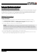
® Dimensions 17.25” 19” 5.875” 1.
® Specifications ANALOG INPUTS Number of Inputs: Connectors: Type: Impedance: Max Input Level (line inputs): CMRR: RTA Mic Preamp Phantom Power: 2 line inputs, 1 RTA mic input 2 female XLR line inputs, 1 female XLR RTA mic input Electronically balanced/RF filtered > 50 kΩ > +20 dBu > 45 dB +15 VDC ANALOG OUTPUTS Number of Outputs: Connectors: Type: Impedance: Max Output Level: Alignment Delay: 6 line outputs Male XLR Electronically balanced, RF filtered 120 Ω +20 dBu Up to 10ms per output channel pair
® Additional Resources dbx Website http://www.dbxpro.com DriveRack PA2 Product Page http://www.dbxpro.com/en-US/products/driverack-pa2 dbx Support http://www.dbxpro.com/en-US/support dbx User’s Forum http://www.dbxpro.
Phone: (801) 566-8800 Website: dbxpro.com Support: dbxpro.com/en-US/support dbx Professional Products is a registered trademark of Harman © 2015 Harman All rights reserved DriverRack® PA2 Owner’s Manual PN: 5044138-B Macintosh, iOS, iPhone, iPad, iTunes, and iTunes Store are trademarks of Apple Computer Incorporated, registered in the U.S. and other countries. Windows is a registered trademark of Microsoft Corporation in the U.S. and other countries. Android and Google Play are trademarks of Google Inc.