® Powered Speaker Optimizer PX Featuring Powered Speakers User Manual
IMPORTANT SAFETY INFORMATION WARNING FOR YOUR PROTECTION PLEASE READ THE FOLLOWING: KEEP THESE INSTRUCTIONS HEED ALL WARNINGS FOLLOW ALL INSTRUCTIONS The symbols shown above are internationally accepted symbols that warn of potential hazards with electrical products. The lightning flash with arrowpoint in an equilateral triangle means that there are dangerous voltages present within the unit.
IMPORTANT SAFETY INFORMATION ELECTROMAGNETIC COMPATIBILITY This unit conforms to the Product Specifications noted on the Declaration of Conformity. Operation is subject to the following two conditions: • • t his device may not cause harmful interference, and this device must accept any interference received, including interference that may cause undesired operation. Operation of this unit within significant electromagnetic fields should be avoided. • use only shielded interconnecting cables. U.K.
Table of Contents Section 1- Introduction.......................... 1 0.1 Defining the DriveRack PX................ 1 0.2 Service Contact Info........................ 2 0.3 Warranty........................................ 3 Section 2- Getting Started...................... 4 2.1 Rear Panel Connections................... 4 2.2 Front Panel Connections.................. 4 2.3 Quick Start.................................... 6 2.4 DriveRack PX Wizard........................ 8 DriveRack® PX Section A - Appendix..
DriveRack® PX Introduction Section 1 Section 1- Introduction The dbx DriveRack® PX Powered Speaker Optimizer has everything you need to get the most out of your stereo powered speaker system. It even includes stereo or mono subwoofer support. With the included dbx M2 measurement mic, Auto-EQ corrects for audible deficiencies in the room environment.
Section 1 Introduction DriveRack® PX 0.2 Service Contact Info If you require technical support, contact dbx Customer Service. Be prepared to accurately describe the problem. Know the serial number of your unit - this is printed on a sticker attached to the bottom panel. If you have not already taken the time to fill out your warranty registration card and send it in, please do so now. Before you return a product to the factory for service, we recommend you refer to the manual.
DriveRack® PX Introduction Section 1 0.3 Warranty This warranty is valid only for the original purchaser and only in the United States. 1. The warranty registration card that accompanies this product must be mailed within 30 days after purchase date to validate this warranty. Proof-of-purchase is considered to be the burden of the consumer. 2. dbx warrants this product, when bought and used solely within the U.S., to be free from defects in materials and workmanship under normal use and service. 3.
Section 2 DriveRack® PX Getting Started Section 2- Getting Started 2.1 Rear Panel Connections SUB OUTPUTS GND R PX UL 60065 120V - 60Hz Manufactured under the following U.S. Patents: 3,789,143; 4,182,993; 6,195,029; 7,203,324. IEC 60065 IEC Power Cord Receptacle The DriveRack® PX comes with a power supply that will accept voltages ranging from 100V120V at frequencies from 50Hz-60Hz. An IEC cord is included. EU versions accept 220V-240V at frequencies from 50Hz-60Hz.
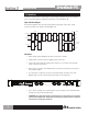
DriveRack® PX Getting Started Section 2 Data Wheel The Data wheel of the DriveRack® PX is used to scroll through the preset menu, load presets, select parameters and edit parameter values. LCD Display The backlit LCD display of the DriveRack® PX provides the user with all of the vital processing information of the DriveRack® PX including: signal routing, effect block editing and Wizard functions. The display will also notify the user if any internal clipping is taking place within the unit.
Section 2 DriveRack® PX Getting Started 2.3 Quick Start For those of you that wish to jump right in, the following information has been provided to act as a quick start guide for optimizing performance of the DriveRack® PX. Signal Path Block Diagram The following diagram shows the logical and intuitive signal path of the input, signal processing modules, and output of the DriveRack® PX.
DriveRack® PX Section 2 Getting Started Once all of the connections have been made and the unit is powered up, you can navigate through the entire signal path of the DriveRack PX from the front panel of the unit. The display provides you with a clear and concise overview of each aspect of the signal path from the input to the output section.
Section 2 Getting Started DriveRack® PX 2.4 DriveRack PX Wizard Now that you have made all of your audio connections and have made yourself familiar with the front-panel navigation of the unit, you can easily optimize your system through the use of the DriveRack® PX Wizards. These allow for quick and accurate venue setups. There are three wizards: Setup, EQ, and AFS. Press hold any button in the Wizard section of the front panel to access them.
DriveRack® PX • Getting Started Section 2 Rotate the wheel to select any one of the numerous MAIN speaker options available. If the speaker being used is not specified in the menu, select CUSTOM. (Note that you can scroll by category by pressing the Select knob and placing the arrow next to the category heading above the speaker name. Press the Select knob again to place the arrow next to the speaker name to scroll by speaker name.
Section 2 Getting Started DriveRack® PX Load New Preset Press Select to Load > New Preset • Press the wheel to load the new preset. The display will look like this: Auto Level • Connect mic to RTA input. Press RTA input button. The display is prompting you to connect an RTA-specific microphone to the front-panel RTA XLR input, and press the button.
DriveRack® PX Getting Started Section 2 Auto-EQ WIZARD • Once you have completed the Setup wizard, you can now proceed to EQ your system. The Auto-EQ Wizard automatically adjusts the response of the system by producing pink noise and adjusting the Graphic EQ until the RTA matches a selected response. (The Auto-EQTM Wizard can be initialized at any time by pressing and holding the button.
Section 2 Getting Started DriveRack® PX either show the graphic EQ or the RTA. Rotating the wheel clockwise and counter clockwise will toggle between the two modes. You can also select either mode as the default in the Utility menu. Regardless, the display will appear something like this: • At this point, the DriveRack® PX will automatically EQ to compensate for the room. AutoEQ can be aborted at any point in the process by pressing the button.
DriveRack® PX Getting Started Section 2 • You will now use the wheel to select the number of fixed filters. This will range from values 0-12. The total number of filters will stay at 12, and the number of live filters will be = Total Num Filters – Num Fixed. Live and Fixed filter types differ in that FIXED mode filters are automatically assigned to a frequency creating feedback, thus remaining at that frequency until cleared by the user.
Section 2 Getting Started DriveRack® PX Fixed Filter Setup Done. In LIVE mode. • To return to preset mode, simply press the or button. For more information regarding feedback elimination, please see the AFS parameters of the Detailed parameters section.
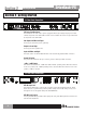
DriveRack® PX Editing Functions Section 3 Section 3 - Editing Functions The DriveRack® PX has been carefully designed and engineered to ensure that all aspects of operation are intuitive and logical. Simply stated, the DriveRack® PX operating system was designed with the user’s best interest in mind. 3.1 Basic Navigation Modes Navigational aspects of the DriveRack® PX are clear, concise and more important: flexible.
PREV PG Section 3 NEXT PG DriveRack® PX Editing Functions SUBHARMONIC PREV PG SUBHARMONIC SETUP COMP/LIMITER NEXT PG SETUP PRESET STORE COMP/LIMITER EQ RECALL UTILITY UTILITY EQ STORE/UTILITY - Press and release to enter the Store menu, which allows the user to store the current state to a user preset. Press and hold to adjust LCD contrast, Auto-EQ plot selection (RTA or GEQ), and Sales Banner WIZARD WIZARD on/off. AFS AFS - Press and release to enter the Feedback processing editor.
DriveRack® PX Editing Functions Section 3 3.5 Navigating the Comp/Limiter Section Navigating the Compressor/Limiter Section From preset mode, press the comp/limiter button to move to either the Compressor or Limiter module(s). Successive presses of COMP/LIMITER button will will toggle between the Compressor and Limiter modules. Navigate through the Pages of the Compressor module by pressing the "Next Page" or "Prev Page" buttons successively until you arrive at the desired Page.
Section 3 DriveRack® PX Editing Functions Navigating the AFS Section Navigating3.7the Advanced Feedback Supression (AFS) Section From preset mode, press the AFS button. Pressing the Data Wheel will select the parameter to be edited. AFS AFS The NEXT and PREV buttons scroll through the pages of selected module.
DriveRack® PX Section 3 Editing Functions Navigating theSection Preset/Recall Section 3.10 Navigating the Recall From preset mode, press and hold the RECALL button. Turn the Data wheel to select a preset; press the Data wheel to load the preset. RECALL PRESET Currently loaded preset All presets RECALL Turn the Data wheel to select a preset. Press the Data wheel to load the preset. Navigating 3.11 Navigating thethe StoreStore Section Section From preset mode, press the STORE button.
Section 4 DriveRack® PX Operating Functions Section 4 - Operating Functions The Operation section of the DriveRack® PX will be your key to successful navigation of the operation of the DriveRack® PX. The following information provides descriptions about preset functions and operating functions of the DriveRack® PX. 4.1 Preset Definition The first step in understanding the capabilities of the DriveRack® PX is to understand the elements involved, that when combined, define a complete “preset.
DriveRack® PX Operating Functions Section 4 - Moves to the previous page in the currently selected menu. - Moves to the next page in the currently selected menu. - Press and release to enter the high-pass and bandpass filter editor. Press and hold to enter the first page of the Powered Speaker Setup Wizard. - Press to enter the dbx 120A Subharmonic Synthesizer editor. - Press to cycle through compressor editor and output limiter editors.
Section 4 Operating Functions DriveRack® PX • Rotating the wheel will change the characters on the currently selected position. • Pressing the wheel will toggle between upper and lowercase letters, numbers or symbols. • Use the and button to move character positions.
DriveRack® PX Detailed Parameters Section 5 Section 5 - Detailed Parameters The DriveRack® PX offers complete editing flexibility, by offering in-depth control over every parameter within each signal processing module. The following section will provide you with descriptions and explanations of all parameters within the DriveRack® PX. 5.1 Stereo Input Graphic EQ EQ On/Off Turns the GEQ on and off.
Section 5 Detailed Parameters DriveRack® PX AFS On/Off Turns the AFS module on and off. If AFS is Off, the filters are bypassed, and the algorithm is halted (the filters are not updated). If AFS is On, the filters are active, and the they are updated according to the current selected mode (Fixed or Live). Clear Live/All This parameter clears the filters. If Clear Live is selected, then (if invoked) the live filters are reset. If Clear All is selected, then (if invoked) all of the filters are reset.
DriveRack® PX Detailed Parameters Section 5 the number of Fixed filters goes down, then the last fixed filter set will be reset. Likewise, if the number of Fixed filters goes up (and thus the number of live filters goes down), then the last live filter set will be reset. The Fixed/Live filter usage will be indicated at the bottom of each page of the feedback elimination effect. ‘F’ indicates an available fixed filter, and ‘L’ indicates an available live filter.
Section 5 Detailed Parameters DriveRack® PX enhanced bottom end with these systems may not be possible and may result in overstressing or even damaging your speakers. It is generally not a good idea to use this feature without a subwoofer. In any case, please refer to your powered mains and powered subwoofer speakers’ frequency response specifications, and avoid forcing them to reproduce low frequencies that they are not designed to reproduce. 5.
DriveRack® PX Detailed Parameters Section 5 Ratio (R) 1.0 to Inf:1 Ratio is the amount the unit reduces the signal level of the sound that is above the threshold. A 2:1 ratio means that if the incoming signal is 2dB over the threshold the unit will compress the signal, and outputs a signal that only goes 1dB over the threshold. For light compression choose a lower ratio, while a heavy compression requires a higher ratio. A setting of Inf:1 makes the compressor act more like a limiter.
Section 5 Detailed Parameters DriveRack® PX 5.5 Filter (SETUP) The Filters are used to divide the input signal into two frequency bands. This allows the user to drive the speaker in its optimum frequency range and send each output separately for more efficient use of amplifier power. Appendix A.5 illustrates each of the available Filters. The signal present at the Main (OUT) outputs can be adjusted using a High-Pass filter.
DriveRack® PX Application Guide Section 6 Section 6 - Application Guide This Application guide section is provided to offer suggested installation applications of the DriveRack® PX that will allow you to optimize peak performance of the units. Note that the 25 included application presets represent the flexibility of the DriveRack® PX. These applications can be used verbatim, or as sample reference guide templates for designing numerous audio applications. 6.1 Mains-Only Setup (No Subs) Hardware 1. 2.
Section 6 DriveRack® PX Application Guide 6.2 Two Mains/One Subwoofer Setup Hardware 1. 2. 3. 4. Make sure that the mixer and powered speakers are turned off prior to powering up the DriveRack® PX. Connect the outputs from the mixer to the inputs of the DriveRack® PX. Connect the main outputs of the DriveRack® PX to the main powered speakers. Connect the Left/Mono sub output of the DriveRack® PX to the sub powered speaker. Software 1. Use the Wizard to set up a specific preset.
DriveRack® PX Application Guide Section 6 6.3 Two Mains/Two Subwoofers Setup Hardware 1. 2. 3. 4. Make sure that the mixer and powered speakers are turned off prior to powering up the DriveRack® PX. Connect the outputs from the mixer to the inputs of the DriveRack® PX. Connect the main outputs of the DriveRack® PX to the main powered speakers. Connect the sub outputs of the DriveRack® PX to the sub powered speakers. Software 1. Use the Wizard to set up a specific preset.
Section 6 DriveRack® PX Application Guide 6.4 Sub with Satellites Setup Hardware 1. 2. 3. 4. Make sure that the mixer and powered speakers are turned off prior to powering up the DriveRack® PX. Connect the outputs from the mixer to the inputs of the DriveRack® PX. Connect the main outputs of the DriveRack® PX to the sub powered speaker. Connect the outputs of the sub speaker to the satellite speakers. Software 1. Use the Wizard to set up a specific preset. Press and hold the button to begin.
DriveRack® PX Appendix Section A Section A - Appendix A.1 Factory Reset In the event that a reset is required, the DriveRack® PX offers you the option of performing a “Soft” or “Hard” reset. The Soft Reset resets all operating parameters except user presets. The Hard Reset Procedure will reset all preset information back to the factory defaults. All Power-Up Functions require a button(s) to be pressed and held as the unit power is turned on. DriveRack PX Power-Up Button Functions Factory (“Hard”) Reset.
Section A Appendix DriveRack® PX • Turning the wheel will select the preset you wish to load at initial reset. • Press the button again when the selection is complete. Normal resetting will continue. System Lock Out • Press and hold at power-up until one of the following messages appears (depending on the current state of system lockout): System Unlocked All user input will be accepted to exit or System Locked! No user input will be accepted to exit or Filter Unlocked.
DriveRack® PX Appendix Section A A.
Section A DriveRack® PX Appendix A.4 Auto-EQ Optimization Tips By using the setup wizard, output gains and output limiter settings are set to match your system. The Auto-EQ can be used to adjust your system to compensate for room effects, and to adjust the response of the entire system to your liking. After allowing Auto-EQ to “pink the room,” your system will sound tighter. The low end will have more definition, the mids will be more intelligible, and the highs can be tamed.
DriveRack® PX Appendix Section A A.
Section A Appendix DriveRack® PX A.7 Preset List / Supported Speakers Preset LIST SUPPORTED SPEAKERS StereoMains Stereo powered full-range speakers. StMainsMSub Stereo powered full-range speakers with a mono powered subwoofer. StMainsSSub Stereo powered full-range speakers with stereo powered subwoofers. Sub wSats Sub with Satellite System PRX515 2 JBL PRX515 full-range speakers PRX515M518 2 JBL PRX515 powered full-range speakers with 1 JBL PRX518 powered subwoofer.
DriveRack® PX Appendix Section A A.8 System Setup and Gain Structure The DriveRack PX offers a wide range of tools for sound system design and setup. These tools can make your system more efficient and better sounding, but to get the best possible sound it is important to use these tools properly. In the DriveRack PX we have included a Wizard setup tool to help in system setup. If you use the Wizard to set up your DriveRack PX it will automatically set the limiters for some powered speaker selections.
Section A Appendix DriveRack® PX of that output (refer to section 5.5 -- Also note that if you turn the outputs down on the DriveRack PX, you should turn up the level on the powered speaker until the clip LED lights again). You have just maximized the gain through your system. These setting should give you maximum gain without clipping, another way of say this is that when the output of your mixer is clipping you will also be at the clip point of your powered speakers.
® 8760 South Sandy Parkway • Sandy, Utah 84070 Phone: (801) 568-7660 • Fax (801) 568-7662 Int’l Fax: (801) 568-7583 E-mail us at: customer@dbxpro.com or visit us on the web at: www.dbxpro.