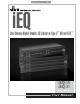
® iEQ Dual Channel Digital Graphic EQ/Limiter w/Type V™ NR and AFS ™ iEQ-15 iEQ-31 User Manual
IMPORTANT SAFETY INSTRUCTIONS WARNING FOR YOUR PROTECTION READ THESE INSTRUCTIONS: CAUTION RISK OF ELECTRIC SHOCK DO NOT OPEN A T T E N T I O N : RISQUE DE CHOC ELECTRIQUE - NE PAS OUVRIR W A R N I N G : TO REDUCE THE RISK OF FIRE OR ELECTRIC SHOCK DO NOT EXPOSE THIS EQUIPMENT TO RAIN OR MOISTURE The symbols shown above are internationally accepted symbols that warn of potential hazards with electrical products.
IMPORTANT SAFETY INSTRUCTIONS U.K. MAINS PLUG WARNING ELECTROMAGNETIC COMPATIBILITY This unit conforms to the Product Specifications noted on the Declaration of Conformity. Operation is subject to the following two conditions: • this device may not cause harmful interference, and • this device must accept any interference received, including interference that may cause undesired operation. Operation of this unit within significant electromagnetic fields should be avoided.
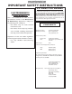
iEQ Table of Contents Table of Contents Defining the iEQ .....................................................i Service Contact Info ...............................................ii Warranty ..................................................................ii Installation Recommendations...............................1 Power Up Quick Key Options ..............................1 Rear Panel Connections .........................................3 Front Panel Connections........................................
iEQ iEQ Operation ®
iEQ Introduction INTRODUCTION Congratulations on your purchase of the dbx Professional Products iEQ Series Graphic Equalizer/Limiter with Type V™ noise reduction and AFS™. With an EQ heritage that has produced countless industry standard patents and dates back more than 30 years, the dbx iEQ 15 and iEQ 31 easily live up to the dbx legacy of uncompromised sonic integrity.
iEQ Introduction Service Contact Info If you require technical support, contact dbx Customer Service. Be prepared to accurately describe the problem. Know the serial number of your unit - this is printed on a sticker attached to the top panel. If you have not already taken the time to fill out your warranty registration card and send it in, please do so now. Before you return a product to the factory for service, we recommend you refer to the manual.
Operation iEQ Installation / User Power-Up Modes Installation Recommendations FOR RACK MOUNT USE ONLY - Install the iEQ in your rack with the provided rack screws. When installed in a rack, the unit should be positioned with enough room (at least one 1U above the and 1U below the unit) to allow proper ventilation. The iEQ should not be mounted above or below anything that generates excessive heat. Ambient temperatures should not exceed 1130F (450C) when equipment is in use.
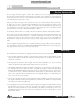
iEQ User Power-Up Modes Cont’d Operation Liv eF Liv Liv eF ilte r L ilte ift O r L ff eF if ilte t Sh or rL t ift Lo ng Live Filter Lift Time Menu - Press the button on CHANNEL 2 to select through selections within menus. The selections for System Lockout are: Live Filter Lift Off, Live Filter Lift Short and Live Filter Lift Long, and will be represented by a lit LED once selected.
Operation iEQ Rear Panel Connections Rear Panel Connections iEQ15 - dual channel 15 band graphic equalizer iEQ31 - dual channel 31 band graphic equalizer Power Cord Receptacle: Connects AC power to the equalizer. Power Switch: Switches the power on and off. Always make audio connections with the power switch in the off position.
iEQ Front Panel Connections Operation iEQ31 - dual channel 31 band graphic equalizer Input Gain Control: This control sets the signal level to the equalizer. It is capable of -12dB to +12dB of gain. Its effect is apparent by viewing the OUTPUT LEVEL BAR GRAPH. EQ Bypass: This switch removes the graphic equalizer section from the signal path. The BYPASS switch does not, however, affect the INPUT GAIN, AFS, or LOW CUT filters.
Operation iEQ Front Panel Connections Cont’d The iEQ 15 and 31 offer the exclusive patent pending AFS (Advanced Feedback Suppression) feedback elimination module. The AFS uses Precision Frequency Detection and state-of-the-art processing to determine the exact portions of a given frequency of your feedback that need to be removed (instead of taking out large sections of your sound). For more detailed information regarding AFS, please visit the AFS white paper section at www.dbxpro.com.
iEQ Basic Connection Operation Basic Connection of the iEQ The iEQ Series Equalizers have balanced inputs and outputs that can be used with any balanced or unbalanced line-level device. To connect the equalizer to your sound system refer to the following steps: • Turn off all equipment before making connections. • Mount equalizer in a standard-width rack. Install the EQs in a rack with the rack screws provided. It can be mounted above or below anything that does not generate excessive heat.
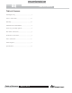
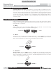
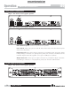
Inputs RF Filter Input Input Gain TYPE IV™ Front Panel Slide Pots Limiter A/D A/D CLIP Detect Type V™ NR EQ Bypass Low Cut Range Relay Bypass DSP Micro Processor D/A AFS (Red LED) Gain Reduction Output meter RF Filter Outputs dbx iEQ 15 and 31 Graphic Equalizer Block Diagram Programmable Logic AFS (Green LED) 7 iEQ User Manual iEQ Block Diagram Operation Block diagram ® ...
iEQ Operation Specifications Specifications Inputs Connectors: Type: Impedance: Max Input Level: CMRR: 1/4” TRS, female XLR (pin 2 hot), and Euroblock Electronically balanced/unbalanced, RF filtered Balanced 40kΩ, unbalanced 20kΩ +22dBu balanced or unbalanced >40dB, typically >55dB at 1kHz Outputs Connectors: Type: Impedance: Max Output Level: 1/4” TRS, male XLR (pin 2 hot), and Euroblock Balanced/unbalanced, RF filtered Balanced 120Ω, unbalanced 60Ω +20dBu balanced/unbalanced into 2kΩ or greater Sys
® A Harman International Company 8760 South Sandy Pkwy. Sandy, Utah 84070 Phone: (801) 568-7660 Fax: (801) 568-7662 Questions or comments? E•mail us at: customer@dbxpro.com or visit our World Wide Web home page at: www.dbxpro.