
User Manual

Zone Controller Wiring
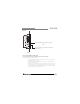
The Zone Controllers, (ZC-1, ZC-2, ZC-3, ZC-4, ZC-6, ZC-7, ZC-8, ZC-9, and ZC-Fire) can
be wired serially or in parallel. To wire in series each Zone Controller must have an iden-
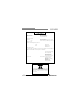
tification or zone number chosen using the DIP switches on the side of the controller (see
diagram A). Each controller must have a unique number chosen although there may be
multiple Zone Controllers controlling a single zone, or a single Zone Controller that con-
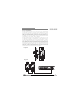
trols multiple outputs. The Zone Controllers can then be wired together and connected
to the DriveRack 220i, 260 or ZonePRO units (see diagram B).
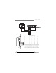
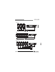
The Zone Controllers may also be wired in parallel with the use of the ZC-BOB. To wire
in parallel (home run cabling), each controller must have a unique identification or num-
ber chosen using the DIP switches on the rear of the panel (see diagram A). To wire in
parallel, each controller must be wired into a port of the ZC-BOB with a connecting wire
going to the DriveRack or ZonePro (see diagram C). Diagram D shows the typical wiring
for ZC-4 Euroblock connections in which the installer needs to use SPDT (single-pole, dou-
ble-throw) switches with one side being connected to 5 volts (+VREF) and the other side
to ground (GND). Diagram E shows the proper way to interface the ZC-Fire to the fire
alarm system. Use only the relay/switch closure or the 5-24V DC inputs. Do not use both
inputs at the same time. For information regarding ZC setup, please see the respective
manual for the Driverack or ZonePro unit that you are setting up.
Diagram A
RJ45
CONNECT
ONLY TO
ZONE CONTROLLE
R
IN P U
T
.
IEC60065
UL-650 0
80-1342-A
RJ45
CONNECT
ONLY
TO
ZONE CONTROLLE
R
IN P U
T
.
IEC60065
UL-650 0
80-1342-A
ID# 1 ID# 4
Diagram B
ZC-Remote Control Wall Controllers
USER GUIDE
®
DriveRack
®
/ZonePRO
™
User Manual
3