THE PROFESSIONAL LIBERTY COLLECTION BFGC-30 models LA COLLECTION LIBERTY PROFESSIONNELLE Modèles BFGC-30 INSTALLATION GUIDE / USER GUIDE GUIDE D’INSTALLATION / GUIDE D’UTILISATION US CA
EN A MESSAGE TO OUR CUSTOMERS Thank you for selecting this DCS Professional “Liberty Collection” Outdoor Appliance. Because of this appliance’s unique features we have developed this Use & Care and Installation Guide. It contains valuable information on how to properly install, operate and maintain your new appliance for years of safe and enjoyable use. To help serve you better, please fill out and submit your Product Registration by visiting our website at www. dcsappliances.
CONTENTS SAFETY PRACTICES & PRECAUTIONS 3-5 OUTDOOR APPLIANCE MODELS 6 BEFORE USING YOUR APPLIANCE 7 INSTALLATION Locating Outdoor Appliance/Built-in Clearances 8-9 Built-in Construction Details 10 Cart Assembly Instructions 11-15 Gas Hook-up 16-19 Leak Testing 20-21 Burner Adjustment 22 Radiant Assembly 23 Sink 24 Side Shelf (optional) 25-26 Installer Checklist 26 USING THE GRILL Lighting Instructions 27 Use of the Grill 27-28 USING THE SIDE BURNER Lighti
EN SAFETY PRACTICES & PRECAUTIONS IMPORTANT SAFETY NOTICE! Certain Liquid Propane dealers may fill liquid propane cylinders for use in the outdoor appliance beyond cylinder filling capacity. This “Overfilling” may create a dangerous condition. IMPORTANT SAFETY NOTICE! Be sure to remove covers from grill, griddle or side burners before attempting to light or use. “Overfilled” tanks can build up excess pressure.
SAFETY PRACTICES & PRECAUTIONS n Never let clothing, pot holders or other flammable materials come in contact with or too close to any grate, burner or hot surface until it has cooled. Fabric may ignite and result in personal injury. n Never attach or disconnect an LP cylinder, or move or alter gas fittings when the grill is in operation or is hot. n Clean and perform general maintenance on the grill twice a year. Watch for corrosion, cracks, or insect activity.
EN SAFETY PRACTICES & PRECAUTIONS n Do not use aluminum foil to line drip pans, grates or radiants. This can severely upset combustion air flow or trap ex- cessive heat in the control area. The result of this can be melted knobs or damaged ignition components. n When using the side burners always use flat bottomed pans which are large enough to cover the side burner. Adjust the flame so that it heats only the bottom of the pan to avoid ignition of clothing.
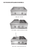
OUTDOOR APPLIANCE MODELS BFGC-30G - All-Grill BFGC-30BGD - Double Side Burner/Griddle BFGC-30BS - Double Side Burner/Sink 6
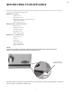
EN BEFORE USING YOUR APPLIANCE 1. Remove all packaging materials and labels from your appliance.
INSTALLATION LOCATING OUTDOOR APPLIANCE/BUILT-IN CLEARANCES LOCATION: When determining a suitable location, take into account concerns such as exposure to wind (If located in a windy area, a wind break must be provided to prevent poor burner performance or product damage.), proximity to traffic paths and keeping any gas or electrical supply lines as short as possible. Locate the outdoor appliance only in a well ventilated area.
EN INSTALLATION LOCATING BUILT-IN CLEARANCES WARNING! The appliances are designed to function in an open area. Recommended minimum clearances should be maintained to all surfaces (combustible* and noncombustible**) for optimum performance. Noncombustible** material within the minimum clearance area could result in discoloration or deterioration.
INSTALLATION BUILT–IN CONSTRUCTION DETAILS grill exhaust 12" (to combustible construction) Bottom of support flange 2" 10-1/16" 3/4" 22-3/4" 25-1/2" Standard layout for non-combustible enclosure: WARNING! 28-1/2" 3" 22-3/4" 18-1/2" 4" x 4" opening for gas supply line 10-1/8" 28" 20" 35-1/2" Max. opening for access doors (see page 9 for ordering information) NOTE: See page 9 for ventilation notes.
EN INSTALLATION CART ASSEMBLY INSTRUCTIONS IMPORTANT: Read all instructions before you begin. Do not jump ahead or skip any step. CAUTION: Some parts have sharp edges; care must be taken when handling the various components to avoid injury. Please read safety information provided in these instructions before beginning assembly. Wear gloves when handling. Two or more people should work together to assemble the cart and All-Grill, Double Side Burner/Sink, or Double Side Burner/Griddle.
INSTALLATION CART ASSEMBLY INSTRUCTIONS Step 1 Link Carts Together (optional) (To link two or more CAD carts, the following instructions must be done first, using the hardware provided, before installing the top modules.) 1. To link your carts together - hand tighten 2 bolts, 4 washers, and 2 nuts on the front and back sides of the carts as shown in Fig. 04. Carefully wrench tighten fasteners once carts are aligned with each other. CAUTION: Once the carts are linked, they cannot be moved.
EN INSTALLATION CART ASSEMBLY INSTRUCTIONS Step 2 Outdoor Appliance Head Preparation 1. First you will need to remove the angle brackets from the side of the unit and replace them with cart mount brackets (Fig. 06). Unit is shipped prepared for island installation. SCREWS 2. Install the bracket tab on both sides of the appliance head using 8 of the 10-24 x 1/2” screws. Install each bracket with 4 screws on each side of the outdoor appliance head (Fig. 07 and 08). Fig. 06 SCREWS Fig. 08 Fig.
INSTALLATION CART ASSEMBLY INSTRUCTIONS 3. Position tabs on side bracket to fit into slots on the cart (be aware of pinch points)(Fig. 12-13). When complete, the leading ledge should sit flush on the top of the cart (no gap)(Fig. 14). PINCH POINT Fig. 14 Fig. 13 Fig. 12 4. Secure the head to rear of cart (Fig. 15) with (2) Phillips-head screws provided (10-24 x 1/2”). 5. Install remaining (3) screws (10-24 x 1/2”) into the front of head to the cart (Fig. 16). 6.
EN INSTALLATION CART ASSEMBLY INSTRUCTIONS Step 4 Gas Hookup - LP Make sure the cart assembly is stable. Open the tank drawer. Place the LP tank into location as shown in Fig. 17. Connect the regulator assembly to the tank connection with all appliances valves in the “OFF” position. Open the tank valve and test for gas leaks (Fig. 18). Fig. 17 Fig. 18 FOR YOUR SAFETY To prevent personal injury or damage to the drawers, do not overload them. The maximum rating of each drawer is 35 pounds.
INSTALLATION GAS HOOK-UP GAS REQUIREMENT Verify the type of gas supply to be used, either natural or LP, and make sure the marking on the appliance rating plate agrees with that of the supply. The rating plate is located on the bottom of the outdoor appliance. Never connect an unregulated gas line to the appliance. You must use the gas regulator provided with the unit even if the supply is controlled. An installer-supplied gas shut-off valve must be installed in an easily accessible location.
EN INSTALLATION GAS HOOK-UP LP GAS HOOK UP (TYPE 1 OR QCC1 REGULATOR): All outdoor appliances orificed for use with LP gas come equipped with a high capacity hose/regulator assemb ly for connection to a standard 20 lb. LP cylinder (Type 1). The LP tank is not included. Connection: 1/2” NPT male with a 3/8” Flare adapter (included). LP Hose with a quick disconnect and fittings are included. Operating pressure: 11.0” W.C.
INSTALLATION GAS HOOK-UP LP TANK RESTRAINT FOR BUILT-IN INSTALLATION If the grill is to be installed in a Built-in application, then the grill must be installed in accordance with the Built–in installation guidelines. If you intend to operate your Built-in grill on LP gas utilizing a 20 lb Type 1 cylinder, then the Built-in LP tank restraint must be installed prior to initial use of the grill. If you do not have one please contact DCS Customer Care at (888) 936-7872 for information on obtaining one.
EN INSTALLATION GAS HOOK-UP STEP 1 Place the tank restraint in the island (Fig. 25). STEP 2 Locate the tank restraint in the island within the recommended area (Fig. 24 and 26). STEP 3 Once located, secure to the bottom of the island using all eight hole locations provided on the restraint. Wood screws can be used for wooden floors or 1/4 inch diameter anchor screws or bolts may be used if the floor is concrete or masonry (Fig. 27). Fig.
INSTALLATION LEAK TESTING - GRILL/GRIDDLE UNIT GENERAL: Although all gas connections on the outdoor appliance are leak tested at the factory prior to shipment, a complete gas tightness check must be performed at the installation site due to possible mishandling in shipment, or excessive pressure unknowingly being applied to the unit. Periodically check the whole system for leaks, or immediately check if the smell of gas is detected. Before Testing: Do not smoke while leak testing.
EN INSTALLATION LEAK TESTING - SIDE BURNER WARNING! Do not smoke while leak testing. Extinguish all open flames. Make a soap solution of one part liquid detergent, and one part water. Never test for leaks with an open flame. For LP units, check with a full cylinder. Make sure all control valves are in the “OFF” position. Turn the gas supply “ON”. Check all connections from the supply line (Fig. 31), or LP cylinder (Fig. 30) up to the manifold pipe assembly (Fig. 32).
INSTALLATION BURNER ADJUSTMENT - GRILL/GRIDDLE UNIT Each outdoor appliance burner is tested and adjusted at the factory prior to shipment; however, variations in the local gas supply or a conversion from one gas type to another may make it necessary to adjust the burners. The flames of the burners should be visually checked and compared to that of the drawing in Fig. 35. Flames should be blue and stable with no yellow tips, excessive noise or lifting.
EN INSTALLATION RADIANT ASSEMBLY RADIANT ASSEMBLY INSTALLATION: 1. Unpack ceramic rods and remove radiant (Fig.37) from the unit. 2. Unlock radiant end cap by pushing it up with two fingers (Fig. 38). 3. Place 18 ceramic rods on the radiant (Fig. 39). 4. Lock radiant end cap (Fig. 40). 5. Place the assembled radiant in the unit (Fig. 41). Fig. 37 IMPORTANT: Placement of the trays in the grill are critical to ensure even cooking performance. Lock radiant end caps must be in the middle of the grill.
INSTALLATION SINK FAUCET INSTALLATION 1. Attach the faucet to the sink as shown in Fig. 42 and 42a. CAUTION: Finger tight first, then use a 1” wrench. Faucet stem Valve Fig. 42 2. Insert drain plug into the drain hole Fig. 43. Rubber gasket Lock washer Nut Fig. 42a Fig. 43 WARNING! The sink is intended for hand washing and cleaning activities. The sink s hould not be used for potable water or food preparation activities unless installed by a certified plumber and per local codes.
EN INSTALLATION SIDE SHELF (Optional accessory) Attach Side Shelf Accessory on Either Side. Side shelf Model CAD-SK can be installed with the head already on the cart. 1. Screw shoulder bolts (2) into the bottom screw holes on the side of the cart only (Fig. 44 and 45). Tighten with 5/32 Allen wrench. SHOULDER BOLT SCREW HOLES Fig. 44 Fig. 45 2. Slide left and right side shelf brackets over the shoulder bolt (Fig. 46) and install top screw attaching the side shelf brackets onto the cart (Fig. 47).
INSTALLATION SIDE SHELF (Optional accessory) 4. Place shelf in the up position and check that it is level. If shelf is not level, adjust side shelf set screw. Set screws can be adjusted using a 3/32 Allen wrench (Fig. 50). Turn the Allen wrench clockwise to raise the shelf. Turn 1/4 turn and review to see if the shelf is level. The set screws in the left and right bracket should be adjusted equally to ensure the shelf sits level (Fig. 51). Fig. 51 Fig.
EN USING THE GRILL LIGHTING INSTRUCTIONS Note: Remove the top grill cover before lighting. Turn all knobs to “OFF”. Turn the main gas supply on. If you smell gas, shut-off gas supply and call for service. Grill Lighting Instructions: The grill knob is connected to the electronic ignition module. Pushing in on the grill knob will activate the ignition module to get a spark. Push and hold the ignition button, turn the selected burner knob to “SEAR”.
USING THE GRILL IMPORTANT - Using the Grill: Grilling requires high heat for searing and proper browning. Most foods are cooked between “MEDIUM” and “LOW” heat setting for the entire cooking time. However, when cooking large pieces of meat or poultry, it may be necessary to turn the heat to a lower setting after the initial browning. This cooks the food through without burning the outside.
EN USING THE SIDE BURNER LIGHTING INSTRUCTIONS First remove the cover and any cooking utensils from the burner grate. Check to see if the burner cap is on correct. Push, turn and hold the control knob in at the “HI” position until the burner is lit or 4 seconds pass (Fig. 55). If the burner doesn’t ignite, wait 5 minutes for any accumulated gas to dissipate then try again. If the burner will not light after several attempts, check the troubleshooting instructions on page 36.
USING THE GRIDDLE The griddle is made from stainless steel, highly polished to provide a smooth cooking surface. It is normal for it to darken with use as oils cook onto the surface to provide a nonstick base or “seasoning”. Since the griddle is made from stainless steel, the surface will not rust. However, after use it may have a rust stain or rust color. The griddle burner is controlled by the gas burner underneath the griddle plate and cycles on and off to maintain the set temperature.
EN USING THE GRIDDLE LIGHTING INSTRUCTIONS Push in and turn griddle control knob to “HI” position. Pushing control knob in activates the ignition module and produces repeated sparking at burner igniter. Holding control knob in also opens the integral safety valve used for this section and starts the flow of gas to burner. Once burner is lit, continue to hold in the control knob for 10 seconds, or until burner remains lit after control knob is released. The knob can then be turned to desired position.
USING THE SINK The sink is available to provide water to your Liberty collection. The faucet is in the “on” position when the lever is turned up (Fig. 58). The faucet is “off” when in the down position as shown in Figure 59. On position Fig. 58 Off position Fig. 59 WARNING! The sink is intended for hand washing and cleaning activities. The sink s hould not be used for potable water or food preparation activities unless installed by a certified plumber and per local codes.
EN CARE AND MAINTENANCE BATTERY REPLACEMENT: 1. Remove drip pan. 2. Pull battery downward (This may require use of pliers.) 3. Re-install upward and push to snap in - Fig. 60. (Polarity is shown in Fig. 61). Note: Battery condition should be checked at least once a year. Fig. 61 Fig. 60 REGULATOR AND HOSE REPLACEMENT The pressure regulator and hose assembly supplied with the unit must be used. If replacements are needed, contact Customer Care for orders at (888) 936-7872.
CARE AND MAINTENANCE If something has spilled into the trays it should be cleaned up as soon as possible to prevent “baked on” food soil. Grease from the griddle or the outdoor appliance drains through the drain tube (Fig. 64) into the tray and liner below. Do not allow the grease to accumulate in the tray as it can be a fire hazard. Clean the tube and tray as soon as they are cool. Clean with hot soapy water. For the tube use a soapy bottle brush.
EN CARE AND MAINTENANCE ORIFICE CLEANING: With the burner removed, remove the orifice and shine a flashlight through the opening to ensure there is no blockage. Use a needle to clear any debris. Be extremely careful not to enlarge the hole or break off the needle. See Fig. 65. Note: When replacing grill burners or orifices following cleaning, confirm orifice penetration into burner as shown in Fig. 66.
CARE AND MAINTENANCE caps are porcelain enamel, follow the directions above that were given for the burner grates. A bristle brush can be used to clean out the toothed burner ports, if necessary. After cleaning, it is important to make sure the location pins on the bottom side of the port ring are properly aligned with the corresponding holes in the base. Incorrect alignment will produce a potentially dangerous flame and poor burner performance (see Fig. 67).
EN TROUBLESHOOTING - OUTDOOR APPLIANCE BEFORE CALLING FOR SERVICE: If the outdoor appliance does not function properly, use the following checklist before contacting your dealer for service. You may save the cost of a service call. Troubleshooting is for general purposes only. If the problem persists and you feel you require service, contact your dealer or the nearest authorized agency to perform service. Only authorized agencies can perform warranty service. Call DCS Customer Care at (888) 936-7872.
TROUBLESHOOTING - SIDE BURNER PROBLEM Burner won’t light when the ignition is pushed. WHAT TO DO Remove the burner grate. Push in the control knob and listen to the electrode while engaging the ignition. There should be a spark from the electrode. When the spark jumps, it makes a ticking sound. If there is no spark........ Could be a dead battery. Try replacing the battery. Or the air gap between an electrode tip and a contact metal is too far (gap should be 1/8”) or dirty. If there is a spark...
EN SERVICE HOW TO OBTAIN SERVICE: For warranty service, please contact your local service provider or DCS Customer Care Representative at (888) 936-7872. Before you call, please have the following information ready: n Model Number (can be found on the inside, right side panel behind the drip pan handle. See page 7.) n Serial Number (can be found on the inside, right side panel behind the drip pan handle. See page 7.) n Code (can be found on the inside, right side panel behind the drip pan handle.
WARRANTY LIMITED WARRANTY When you purchase a new DCS Grill by Fisher & Paykel, you automatically receive a One Year Limited Warranty covering parts and labor for the entire product, and a Five Year Comprehensive Warranty covering the radiant trays, radiant tray side rails and drip pans for servicing within the 48 mainland United States, Hawaii, Washington D.C. and Canada. Should structural deterioration occur to the degree of non-performance, a replacement will be furnished.
EN WARRANTY (continued) 5. Change the set-up of the Product. 6. Unauthorized modifications of the Product. 7. Noise or vibration that is considered normal, for example, drain/fan sounds, regeneration noises or user warning beeps. 8. Correcting damage caused by pests, for example, rats, cockroaches etc. B. Defects caused by factors other than: 1. Normal domestic use or 2. Use in accordance with the Product’s Use and Care Guide. C.
NOTES 42
FR À L’INTENTION DE NOS CLIENTS Nous vous remercions d’avoir choisi cet appareil d’extérieur de la « Collection Liberty » professionnelle de DCS. Nous avons conçu ce Manuel d’utilisation et d’entretien pour expliquer les fonctions uniques de ces appareils. Ce manuel contient des informations extrêmement utiles sur la façon correcte de faire fonctionner votre nouvel appareil et d’en faire l’entretien. Vous pourrez ainsi en profiter pendant des années d’emploi sûr et agréable.
TABLE DES MATIÈRES MESURES DE SÉCURITÉ ET DE PRÉCAUTION 3-6 MODÈLES D’APPAREILS D’EXTÉRIEUR 7 AVANT D’UTILISER L’APPAREIL 8 INSTALLATION Emplacement de l’appareil d’extérieur et des dégagements 9-10 Détails d’une construction intégrée 11 Instructions de montage de chariot 12-16 Branchement de gaz 17-20 Test de détection des fuites 21-22 Réglage des brûleurs 23 Ensemble de radiant 24 Évier 25 Tablette latérale 26-27 Liste de contrôle de l’installateur 27
FR MESURES DE SÉCURITÉ ET DE PRÉCAUTION IMPORTANTE CONSIGNE DE SÉCURITÉ! Certains fournisseurs de propane liquide peuvent remplir les bonbonnes de propane liquide de l’appareil d’extérieur au-delà de leur capacité. Ce trop-plein peut créer une situation dangereuse. IMPORTANTE CONSIGNE DE SÉCURITÉ! Assurez-vous de retirer tous les couvercles du gril, de la plaque chauffante ou des brûleurs latéraux avant d’allumer ou d’utiliser l’appareil.
MESURES DE SÉCURITÉ ET DE PRÉCAUTION n Ne rangez pas d’objets pouvant intéresser les enfants autour ou en dessous d’appareil d’extérieur, dans le chariot ou une enceinte de maçonnerie. Ne laissez jamais les enfants ramper à l’intérieur d’un chariot ou d’une enceinte. n Ne laissez jamais des vêtements, gants ou autres matériaux inflammables en contact ou à proximité d’une outdoor cooktope, d’un brûleur ou d’une surface chaude tant qu’ils n’ont pas refroidi.
FR MESURES DE SÉCURITÉ ET DE PRÉCAUTION EMPLACEMENT D’APPAREIL D’EXTÉRIEUR FLUX D'ÉVENT DE SORTIE ÉV AC UA TI O N ÉVACUATION DU GRIL BRÛLEUR R, AI D' ION X S LE U S FL MI IPA AD INC PR VENT FLAMME FLUX D'AIR PRÉFÉRÉ Hauteur deLIFT flamme FLAME VENT n Si vous utilisez les brûleurs latéraux, servez-vous toujours de casseroles à fond plat assez grandes pour couvrir le brûleur latéral. Ajustez la flamme pour qu’elle ne chauffe que le fond du récipient afin de ne pas mettre le feu aux vêtements.
MESURES DE SÉCURITÉ ET DE PRÉCAUTION n Ne déplacez pas l’appareil durant son utilisation. n Cet appareil est conçu pour un usage en plein air uniquement ! Ne faites pas fonctionner dans des endroits clos. Ce qui pourrait entraîner une accumulation de monoxyde de carbone susceptible de provoquer des blessures voire la mort. n Lors de l’utilisation d’un gril, veillez à ce que toutes les pièces de l’unité soient fermement en place et que le gril soit stable (de manière à ne pas pouvoir basculer).
FR MODÈLES D’APPAREILS D’EXTÉRIEUR BFGC-30G - Tout gril BFGC-30BGD - Brûleurs latéraux double et Plaque chauffante BFGC-30BS - Brûleurs latéraux double et Évier 7
AVANT D’UTILISER L’APPAREIL 1. Retirez tous les matériaux d’emballage et les étiquettes de l’appareil.
FR INSTALLATION EMPLACEMENT DE L’APPAREIL D’EXTÉRIEUR ET DES DÉGAGEMENTS EMPLACEMENT : Pour déterminer un emplacement approprié, vous devez tenir compte de plusieurs éléments : exposition au vent (si l’appareil est situé dans une zone venteuse, un coupe-vent doit être fourni pour éviter un mauvais fonctionnement des brûleurs ou tout dommage du produit), proximité de chemins de circulation, nécessité de garder les conduites d’alimentation en gaz ou électrique le plus court possible.
INSTALLATION EMPLACEMENT DES DÉGAGEMENTS AVERTISSEMENT! Les appareils sont conçus pour fonctionner à l’extérieur. Prévoyez des dégagements minimum recommandés pour toutes les surfaces (combustibles* et non combustibles**) pour une performance optimale. Le matériau non combustible** dans la zone de dégagements minimum pourrait entraîner une décoloration ou une détérioration.
FR INSTALLATION DÉTAILS D’UNE CONSTRUCTION INTÉGRÉE évacuation du gril 30,5 cm/12 po (dégagement avec une construction combustible) Fond de la bride de soutien 5,08 cm/ 2 po 25,56 cm/10 1/16po 57,79 cm/22 3/4po 1,91cm/3/4 po 64,77 cm/25 1/2 po Disposition standard pour une enceinte non combustible : AVERTISSEMENT! 72,39 cm/28 1/2po 7,6 cm/3 po 57,79 cm/22 3/4 po Ouverture de 5,08 x 5,08 cm (4 x 4 po) pour la conduite d'alimentation en gaz 46,99 cm/ 18 1/2 po 25,72 cm/ 10 1/8 po 50,8 cm/20 po
INSTALLATION INSTRUCTIONS DE MONTAGE DE CHARIOT IMPORTANT: Lisez toutes les instructions avant de commencer. Évitez de sauter des étapes. ATTENTION : Certaines pièces ont des bords coupants; faites attention lorsque vous manipulez les différents composants pour éviter de vous blesser. Veuillez lire les consignes de sécurité de ce manuel avant de commencer l’assemblage. Portez des gants. Il faut deux personnes ou plus pour assembler le chariot et l’appareil d’extérieur.
FR INSTALLATION INSTRUCTIONS DE MONTAGE DE CHARIOT Étape 1 Regroupement de chariot (en option) (Pour regrouper deux chariots CAD ou plus, procédez aux instructions suivantes en premier, à l’aide de la visserie fournie, avant d’installer les modules supérieurs.) 1. Pour regrouper les chariots – serrez à la main 2 boulons, 4 rondelles et 2 écrous sur le devant et l’arrière des chariots comme l’indique la Fig. 05.
INSTALLATION INSTRUCTIONS DE MONTAGE DE CHARIOT Étape 2 Préparation de la tête de l’appareil d’extérieur 1. Il vous faut d’abord retirer les équerres du côté de l’appareil et les remplacer par les supports de fixation du chariot (Fig. 06). L’appareil est expédié préparé pour une installation autoportante. VIS 2. Installez la languette de support de part et d’autre de la tête de l’appareil à l’aide de 8 des vis 10-24 x 1/2”.
FR INSTALLATION INSTRUCTIONS DE MONTAGE DE CHARIOT 3. Positionnez les languettes sur le support latéral pour rentrer dans les fentes sur le chariot (faites attention aux points de pincement) (Fig. 12 -13). Une fois terminé, la pièce d’appui doit affleurer le haut du chariot (sans appui) (Fig. 14). POINTS DE PINCEMENT Fig. 14 Fig. 13 Fig. 12 4. Fixez la tête à l’arrière du chariot (Fig. 15) à l’aide de (2) vis cruciformes fournies (10-24 x 1/2”). 5.
INSTALLATION INSTRUCTIONS DE MONTAGE DE CHARIOT Étape 4 Branchement du gaz – Propane Assurez-vous que l’ensemble de chariot est stable. Ouvrez le tiroir de la bouteille. Placez la bouteille de propane comme l’indique la Fig. 17. Raccordez l’ensemble du régulateur à la connexion de bouteille avec toutes les valves de l’appareil en position « OFF ». Ouvrez le robinet de la bouteille et vérifiez l’absence de fuite de gaz (Fig. 18). Fig. 17 Fig.
FR INSTALLATION BRANCHEMENT DU GAZ EXIGENCES CONCERNANT LE GAZ Vérifiez le type de gaz à utiliser (gaz naturel ou propane) et assurez-vous que les indications figurant sur la plaque signalétique de l’appareil sont conformes à celles de l’alimentation. La plaque signalétique est située sur le bas de l’appareil d’extérieur. Ne connectez jamais un tuyau à gaz non régulé à l’appareil. Vous devez utiliser le détendeur de gaz fourni avec l’unité, même si l’alimentation est contrôlée.
INSTALLATION BRANCHEMENT DU GAZ BRANCHEMENT DU PROPANE (RÉGULATEUR DE TYPE 1 OU QCC1) : Tous les appareils d’extérieur dont les orifices sont prévus pour du propane sont équipés d’un tuyau et d’un régulateur de haute capacité pouvant être connectés à une bouteille standard de propane de 9 kg (20 lb) (Type 1). La bouteille de propane n’est pas incluse. Connexion : Raccord mâle 3/8 po NPT avec adaptateur évasé 3/8 po (inclus). Un tuyau de propane avec déconnexion rapide et des raccords sont inclus.
FR INSTALLATION BRANCHEMENT DU GAZ INSTRUCTIONS RELATIVES À LA BOUTEILLE DE PROPANE POUR INSTALLATIONS ENCASTRÉES Pour installer le gril dans une application encastrée, il doit être installé conformément aux directives d’installation encastrée figurant dans le guide d’utilisation et d’entretien accompagnant le gril. Si le gril va être utilisé avec du gaz propane utilisant une bouteille de 20 lb Type 1, il faut alors installer le dispositif de retenue de la bouteille de propane, réf.
INSTALLATION BRANCHEMENT DU GAZ STEP 1 Placez le dispositif de retenue de bouteille dans l’îlot (Fig. 25). STEP 2 Situez le dispositif de retenue de bouteille dans l’îlot à l’intérieur de la zone recommandée (Fig. 24 et 26). STEP 3 Une fois situé, fixer sur le bas de l’îlot à l’aide des huit emplacements de trous prévus sur le dispositif de retenue. Utilisez des vis à bois pour les planchers en bois ou des vis d’ancrage ou des boulons pour les sols en béton ou en maçonnerie (Fig. 27). Fig.
FR INSTALLATION TEST DE DÉTECTION DES FUITES – UNITÉ DE GRILLE ET DE PLAQUE CHAUFFANTE GÉNÉRALITÉS : Bien que toutes les connexions de gaz du gril soient testées en usine avant l’expédition, une vérification complète doit être effectuée sur le site d’installation, pour s’assurer qu’il n’y a pas de fuites, au cas où l’appareil aurait été malmené durant le transport ou qu’il aurait subi une pression excessive.
INSTALLATION TEST DE DÉTECTION DES FUITES – BRÛLEUR LATÉRAUX AVERTISSEMENT! Ne fumez pas pendant le test. Éteignez toute flamme vive. Préparez une solution savonneuse composée à moitié de détergent liquide et à moitié d’eau. Ne vérifiez jamais la présence de fuites près d’une flamme vive. Pour les appareils à propane, effectuez la vérification avec une bouteille pleine. Assurez-vous que les valves de réglage sont en position « OFF » (fermé). Ouvrez l’alimentation en gaz « ON ».
FR INSTALLATION RÉGLAGE DU BRÛLEUR DU GRIL – UNITÉS DE GRILLE ET DE PLAQUE CHAUFFANTE Chaque brûleur du gril est testé et réglé en usine avant d’être expédié; toutefois, des variations au niveau de l’alimentation en gaz locale ou de la conversion d’un gaz à un autre peut nécessiter un nouveau réglage. Les flammes des brûleurs doivent être vérifiées visuellement et comparées à celles du schéma de la figure 35.
INSTALLATION INSTALLATION DE L’ENSEMBLE DU RADIANT INSTALLATION DE L’ENSEMBLE DU RADIANT : 1. Déballez les tiges en céramique et retirez le radiant (Fig. 37) de l’appareil. 2. Déverrouillez le couvercle du radiant en le poussant de deux doigts (Fig. 38). 3. Placez 18 tiges en céramique sur le radiant (Fig. 39). 4. Verrouillez le couvercle du radiant (Fig. 40). 5. Placez le radiant assemblé dans l’appareil (Fig. 41). Fig.
FR INSTALLATION ÉVIER INSTALLATION DES ROBINETS 1. Attachez le robinet à l’évier comme l’indiquent les Fig. 42 et 42a. ATTENTION : Serrez d’abord à la main puis utilisez une clé de 1”. Tige de robinet Valve Fig. 42 2. Insérez la bonde dans l’orifice d’évacuation Fig. 43. Joint en caoutchouc Rondelle frein Écrou Fig. 42a Fig. 43 AVERTISSEMENT! L’évier est prévu pour se laver les mains et nettoyer.
INSTALLATION TABLETTE LATÉRALE (accessoire en option) Attachez l’accessoire de tablette latérale d’un côté ou de l’autre. Il est possible d’installer la tablette latérale Modèle CAD-SK avec la tête déjà sur le chariot. 1. Vissez (2) boulons à épaulement dans les orifices pour vis inférieurs sur le côté du chariot uniquement (Fig. 44 et 45). Serrez à l’aide d’une clé Allen de 5/32. TROUS DE VIS DES BOULONS À ÉPAULEMENT Fig. 44 Fig. 45 2.
FR INSTALLATION TABLETTE LATÉRALE (accessoire en option) 4. Placez la tablette en position relevée et vérifiez qu’elle est de niveau. Si la tablette n’est pas de niveau, ajustez la vis de réglage de la tablette latérale. Pour ajuster les vis de réglage, utilisez une clé Allen 3/32 (Fig. 50). Tournez la clé Allen dans le sens des aiguilles d’une montre pour relever la tablette. Tournez 1/4 de tour et inspectez pour voir si la tablette est de niveau.
UTILISATION DU GRIL INSTRUCTIONS D’ALLUMAGE Remarque : Retirez le couvercle du gril supérieur avant d’allumer le gril. Mettez tous les boutons sur « OFF ». Ouvrez l’alimentation en gaz. Si vous sentez une odeur de gaz, fermez le gaz et appelez le service technique. Instructions d’allumage du gril : Le bouton du gril est raccordé au module d’allumage électronique. Enfoncer le bouton du gril activera le module d’allumage pour obtenir une étincelle.
FR UTILISATION DU GRIL IMPORTANT Utilisation du gril : La cuisson sur gril exige un feu vif pour rôtir les aliments et les braiser correctement. La plupart des aliments sont cuits à feu modéré pendant tout le temps de cuisson. Cependant, pour cuire de gros morceaux de viande ou de volaille, il peut s’avérer nécessaire de baisser le feu après le braisage initial. Cela permet de cuire la nourriture sans en brûler l’extérieur.
UTILISATION DU DRÛLEUR LATÉRAL INSTRUCTIONS D’ALLUMAGE Commencez par retirer le couvercle et les ustensiles de cuisson de la grille des brûleurs. Vérifiez que le capuchon de brûleur est mis correctement. Enfoncez, tournez et maintenez le bouton de réglage en position « HI » jusqu’à ce que le brûleur soit allumé ou que 4 secondes se soient écoulées (Fig. 55). Si le brûleur ne s’allume pas, patientez 5 minutes avant d’essayer de nouveau, afin de laisser le temps au gaz accumulé de se dissiper.
FR UTILISATION DE LA PLAQUE CHAUFFANTE La plaque chauffante est fabriquée en acier inoxydable, polie étincelante, pour fournir une surface de cuisson lisse. Il est normal qu’elle fonce à l’usage avec les huiles qui cuisent sur la surface pour fournir une base antiadhésive ou un « apprêtage ». Étant donné que la plaque chauffante est en acier inoxydable, elle ne rouillera pas. Toutefois, à l’usage, elle peut avoir des tâches de rouille ou une couleur de rouille.
UTILISATION DE LA PLAQUE CHAUFFANTE INSTRUCTIONS D’ALLUMAGE Enfoncez et tournez le bouton de réglage de la plaque chauffante en position « HI ». Enfoncer le bouton de réglage activera le module d’allumage et produira des étincelles répétées à l’allumeur du brûleur. Maintenir le bouton de réglage enfoncé ouvre également la valve de sécurité intégrée utilisée pour cette section et démarre l’écoulement du gaz vers le brûleur.
FR UTILISATION DE L’ÉVIER L’évier est disponible pour fournir de l’eau à la Collection Liberty. Le robinet est en position « on » lorsque le levier est relevé (Fig. 58). Le robinet est en position « off » lorsqu’il est abaissé comme l’indique la Figure 59. Position « On » Fig. 58 Position « Off » Fig. 59 AVERTISSEMENT! L’évier est prévu pour se laver les mains et nettoyer.
ENTRETIEN ET NETTOYAGE REMPLACEMENT DE LA PILE : 1. Retirez le ramasse-gouttes. 2. Tirez la pile vers le bas (servez-vous d’une pince aubesoin). 3. Remettez-la en place vers le haut et poussez jusqu’à entendre un déclic, Fig. 60. (La polarité est indiquée à la Fig. 61.) Remarque : Vérifiez l’état de la pile au moins une fois par an. REMPLACEMENT DU RÉGULATEUR ET DU TUYAU Fig. 61 Fig. 60 Vous devez utiliser le régulateur de pression et le tuyau fournis avec l’unité.
FR ENTRETIEN ET MAINTENANCE Nettoyez tout débordement dans les plateaux aussi rapidement que possible pour éviter des taches d’aliments « incrustés ». La graisse de la plaque chauffante ou de l’appareil d’extérieur s’écoule par le tube de vidange (Fig. 63) dans le plateau et le revêtement en dessous. Ne laissez pas la graisse s’accumuler dans le plateau car elle peut être un risque d’incendie. Nettoyez le tube et le plateau dès qu’ils sont refroidis. Nettoyez à l’eau chaude savonneuse.
ENTRETIEN ET MAINTENANCE NETTOYAGE DE L’ORIFICE : Le brûleur étant retiré, enlevez l’orifice et inspectez l’ouverture avec une lampe de poche pour vous assurer qu’elle n’est pas bloquée. Dégagez les débris à l’aide d’une aiguille. Faites extrêmement attention de ne pas élargir le trou ou de casser l’aiguille. (Voir Fig. 65) Remarque : Lorsque vous replacez les brûleurs du gril ou les orifices après le nettoyage, assurez-vous que les orifices pénètrent bien dans le brûleur tel qu’indiqué à la figure 66.
FR ENTRETIEN ET MAINTENANCE Assurez-vous que tous les boutons des brûleurs sont en position « OFF » avant d’essayer de nettoyer les brûleurs. Les brûleurs ont été conçus pour être faciles à nettoyer. Une fois la grille et les brûleurs refroidis, retirez la grille. Le capuchon de brûleur et la couronne en laiton peuvent être facilement enlevés. Lavez ces pièces dans de l’eau savonneuse chaude, rincez et séchez soigneusement.
DÉPANNAGE – APPAREIL D’EXTÉRIEUR AVANT D’APPELER LE SERVICE TECHNIQUE : Si l’appareil d’extérieur ne fonctionne pas correctement, utilisez cette liste de contrôle avant de contacter votre distributeur. Vous pourriez ainsi vous épargner le coût d’une demande de service. Le dépannage couvre les problèmes d’ordre général seulement. Si le problème persiste et que vous avez besoin d’assistance, contactez votre distributeur ou le centre de service agréé le plus proche.
FR DÉPANNAGE – BRÛLEUR LATÉRAL PROBLÈME SOLUTION Le brûleur ne s’allume pas lorsqu’on enfonce le bouton d’allumage. Retirez la grille du brûleur. Enfoncez le bouton de réglage étant sur « OFF », écoutez l’électrode tout en enfonçant le bouton d’allumage. Vous devriez entendre une étincelle jaillir à l’intérieur du capuchon de l’électrode. Quand cela se produit, l’étincelle fait comme un son de tic-tac. S’il n’y a pas d’étincelle........ La pile pourrait être à plat.
SERVICE POUR L’OBTENTION DU SERVICE DE GARANTIE : Pour le service sous garantie, contactez votre distributeur ou le Centre de service à la clientèle DCS au (888) 936-7872. Avant d’appeler, veuillez avoir les informations suivantes à portée de main : n Numéro de modèle (peut se trouver sur le panneau latéral intérieur droit, derrière la poignée du ramasse-gouttes. Voir page 8.) n Numéro de série (peut se trouver sur le panneau latéral intérieur droit, derrière la poignée du ramasse-gouttes. Voir page 8.
FR GARANTIE GARANTIE LIMITÉE Lorsque vous faites l’achat d’un DCS Grill by Fisher & Paykel neuf, vous recevez automatiquement une Garantie limitée d’un an couvrant les pièces et la main d’œuvre pour tout le produit, et une Garantie extensive de cinq ans couvrant les plateaus radiants du gril, les couvercles du radiant et le ramasse-gouttes pour entretien dans les 48 États continentaux, Hawaï, Washington D.C. et le Canada.
GARANTIE (suite) B. Défauts causés par des facteurs autres que : 1. Utilisation domestique normale ou 2. Utilisation conformément aux indications du guide d’utilisation et d’entretien du produit. C. Défauts du produit pour cause d’accident, négligence, mauvaise utilisation, incendie, inondation ou calamité naturelle. D. Les coûts des réparations effectuées par des techniciens non autorisés ou le coût de correction de ces réparations non autorisées. E.
REMARQUE FR
WWW.DCSAPPLIANCES.COM © Fisher & Paykel Appliances 2019. All rights reserved. The product specifications in this booklet apply to the specific products and models described at the date of issue. Under our policy of continuous product improvement, these specifications may change at any time. You should therefore check with your Dealer to ensure this booklet correctly describes the product currently available. © Fisher & Paykel Appliances 2019. Tous droits réservés.