PROFESSIONAL GRILL CART CAD1 models INSTALLATION GUIDE / USER GUIDE US CA
CONTENTS Safety and warnings 2 Introduction 4 Model identification & dimensions 5 Shipping inspection 6 Locating the cart 7 Cart assembly instructions 7 Components 8 Cart assembly instructions 9 Side shelf assembly instructions (optional) Using the cart 14 15 Removing the drawers 15 Re-installing the drawers 15 Freezer pack (optional, kit #70696A) 16 Care and maintenance 17 Service & warranty 18 IMPORTANT! SAVE THESE INSTRUCTIONS The models shown in this user guide may not be
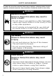
SAFETY AND WARNINGS To reduce the risk of fire, electrical shock, injury to persons, or damage when using the appliance, follow the important safety instructions listed below: hazard or other injury. ! WARNING! Explosion Hazard Failure to follow this advice may result in injury or death. • Do not store or use gasoline or other flammable vapors and liquids inside or in the vicinity of this or any other appliance.
SAFETY AND WARNINGS z z z z Do not allow children or pets to play in or around the cart. To prevent personal injury or damage to the drawers, do not overload them. The maximum rating of each drawer is 35 pounds. Do not store items of interest to children above or on the inside of any cart. Children could be seriously injured if they should climb onto or into the cart to reach these items. To prevent injury from tipping, all Series 9 grills must only be used with either CAD136E or CAD1-48E model carts.
INTRODUCTION Thank you for selecting this DCS by Fisher & Paykel Grill Cart. This installation and user guide contains valuable information on how to properly install, and maintain your new Professional Grill Cart for years of safe and enjoyable use. For your convenience, product questions can be answered by a DCS Customer Care Representative at www.dcsappliances.com, or email: customer.care@fisherpaykel.com.
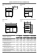
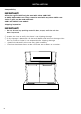
MODEL IDENTIFICATION & DIMENSIONS CAD1-30 and side shelf CAD1-36/36E Front gFront g g gf fA A A A A A A A f f CAD1-48/48E CAD1-30, CAD1-36/36E and CAD1-48/48E Front Profile A A D D E A A D D E E E c b c b c c b b PRODUCT DIMENSIONS CAD1-30 CAD1-36/36E CAD1-48/48E IN MM IN MM IN MM 30 762 36 914 48 1219 35 1/2 902 35 1/2 902 35 1/2 902 C Height of cart chasis (excluding wheels) 32 816 32 816 32 816 D Overall depth of cart 25 1/2 648 25 1/2 648 25 1/2
INSTALLATION Compatibility IMPORTANT! All Series 9 grills MUST only be used with either CAD1-36E or CAD1-48E model carts. They cannot be used with any other CAD1 carts. Series 7 grills can be used with both CAD1 and CAD1-E cart models. Shipping inspection IMPORTANT! z Do not discard any packing material (box, straps) until the unit has been inspected. 1 Inspect the Cart to verify that there is no shipping damage. 2 If any damage is detected, call the retail dealer and initiate a damage claim.
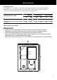
INSTALLATION Locating the cart For proper use, this product should be installed/positioned on a flat ground or patio. Unevenness such as bumps, cracks and protrusions should be 1/4” or less. Refer to illustration and the below table for required flat area dimensions.
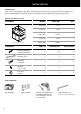
INSTALLATION Components Your cart is packaged in one box. The box contains your cart and a universal hardware kit to be used for grill installation and may contain extra hardware for your convenience. Table of quantity of parts CONTENTS MODEL PART NO. QTY CAD1-30 71131 1 CAD1-36 71132 1 CAD1-36E 71407 1 CAD1-48 71133 1 CAD1-48E 71408 1 CAD1-30 CAD1-36/36E CAD1-48/48E 13 16 17 Bracket, Tab 2 2 4 Bolt Hex 1/4-20-12” 2 2 2 Washer .313 x .
INSTALLATION Cart assembly instructions Linking carts together (optional) To link two or more CAD1 carts, the following instructions must be done first, using the hardware provided, before installing the top modules. IMPORTANT! Once the carts are linked, they cannot be moved. Moving the carts once linked could damage the carts. 1 Hand tighten two bolts, four washers, and two nuts on the front and back sides of the carts as shown. 2 Carefully wrench tighten fasteners once carts are aligned with each other.
INSTALLATION Outdoor appliance head preparation IMPORTANT! For the CAD1-48/48E there are two sets of brackets. If you have the BGB48-BQR, use the brackets labeled LEFT-48 BQR and RIGHT-48 BQR. If you have the BGB48-BQAR, use the brackets labeled 48-BQAR. 1 2 First you will need to remove the angle brackets from the side of the unit and replace them with cart mount brackets. Note: unit is shipped prepared for island installation.
INSTALLATION Position tabs on side bracket to fit into slots on the cart. When complete, the landing ledge should sit flush on the top of the cart. 3 Pinch point 4 Secure the head to rear of cart with Phillipshead screws provided (10-24 x 1/2”). Front end screw installation 1 Install remaining screws (10-24 x 1/2”) into the front of head to the cart. 2 Slide drip tray/pan back into place.
INSTALLATION Transformer installation (for Series 9 grills only) Your Series 9 grill comes supplied with a power transformer for ignition and internal lighting, which is concealed in a box with an attached power supply cord. It is recommended that the transformer is mounted to the rear panel of the CAD1-E cart using the 4 holes provided. HZ 60 Hz VOLTAGE AMPS 120V 15A IMPORTANT! Use only a Ground Fault Interrupter (GFI) protected circuit with this transformer.
INSTALLATION Gas hook-up – LP Place your 20 lb cylinder (type 1) into the tank retention device as shown. Refer to your product user guide for detailed gas connection guidance. IMPORTANT! z z To prevent personal injury or damage to the drawers, do not overload them. The maximum rating of each drawer is 35 pounds. Do not push down on the top of the drawers. The unit could tip foward.
INSTALLATION Side shelf assembly instructions (optional) Optional attach side shelf accessory on either side Note: side shelf model CAD1-SK can be installed with the head already on the cart. Shoulder bolt screw location 1 Screw two shoulder bolts into the bottom screws on the side of the cart. Tighten with 5/32 Allen wrench. 2 Slide left and right side shelf brackets over the shoulder bolt and install top screw attaching the side shelf brackets onto the cart. Tighten with Phillips screwdriver.
USING THE CART Removing the drawers IMPORTANT! To prevent personal injury or damage to the drawers, do not overload them. The maximum rating of each drawer is 35 pounds. To remove the drawers, pull them out until their slider latch is visible. Carefully push the latch down on the left side while pulling up on the latch on the right side and pull the drawer completely out of the frame.
USING THE CART 3 While holding the drawer up by the handle, pull the glides from the drawer cavity out over the drawer glide until they click. 4 As you push the drawers in, you will encounter moderate resistance. Continue to push the drawer all the way in to complete the engagement process. The drawer will now glide smoothly in and out with light effort. Rack & rack cover Install the two racks provided into the opening by sliding them onto the rollers on the sidewalls of the left cavity.
CARE AND MAINTENANCE All parts of the Professional Grill Cart can be cleaned with hot soapy water, rinsed, dried and buffed to a shine with a soft, heavy cloth. Always try this first, as it is the mildest cleaning procedure. 1 Use the mildest cleaning procedure first. Some brands of cleaners of the same type are harsher than others, read their directions. A scent or a propellant can make a difference in the product, read the ingredients. Try on a small area first.
SERVICE & WARRANTY For warranty service, please contact your local service provider or DCS Customer Care Representative at www.dcsappliances.com, please have the following information ready: z z z z z Model number (can be found on the inside, left wall of the tank drawer). Serial number (can be found on the inside, left wall of the tank drawer). Code (can be found on the inside, left wall of the tank drawer). Date of installation. A brief description of the problem.