
Installation Guide


4
CAD-BND to a CAD Cart:
Position the CAD cart in the intended position. 1.
Place the three cardboard lifters from the packaging on the ground next to the cart in the approximate 2.
position of the Bend Unit (Fig. 08).
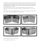
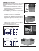
Place the Bend Unit on top of the lifters, adjacent to the CAD cart. To ensure proper alignment, make sure 3.
the back of the cart is ush with the rear wall or door of the Bend Unit (Fig. 09).
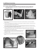
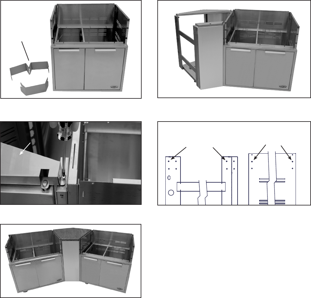
Remove the door from the Bend Unit by removing the screw holding the rear riser bracket near the door 4.
hinge (Fig. 10). This must be done to provide access to the mounting holes.
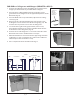
Secure the two together using (2) hex bolts (1/4-20 x 1/2”), (4) washers (5/16 x 3/4), and (2) hex nuts 5.
(1/4-20) through the top/rear set of holes in the Bend Unit and middle holes in the cart (Fig.11).
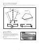
Position the second cart on the other side of the Bend Unit and secure to the Bend Unit as in Step 5.6.
Once the Bend Unit and both carts are secured, re-install the door, remove the cardboard lifters and place 7.
the solid surface on top.
Once complete the units should look like Fig. 12.8.
Fig. 09
Fig. 10
Rear riser bracket
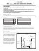
Fig. 08
Cardboard
lifters in
intended
location of
Bend Unit
FRONT
REAR
SIDE VIEW
FRONT
REAR
Fig. 11
Fig. 12
BEND UNIT CAD CART
Use shaded holes
Use shaded holes
Front
Rear