dCS 954 Digital to Analogue Converter User Manual Standard software version 1.5x P3D software version 1.36 June 2000 © 1997, 1999, 2000 dCS Ltd All rights reserved. Reproduction of this manual in any manner whatsoever, without the written permission of dCS1 is strictly forbidden. Additional copies of this manual may be obtained from dCS. Information contained in this manual is subject to change without notice, and whilst it is checked for accuracy, no liabilities can be accepted for errors.
dCS 954 User Manual dCS Ltd Manual part no: DOC136954 iss 2B1 Contact dCS on + 44 1799 531 999 (inside the UK replace + 44 with 0) Manual for Standard Software Version 1.5x June 2000 Page 2 file 135954ma2b1.pdf available from website email to: more@dcsltd.co.uk web site: www.dcsltd.co.
dCS 954 User Manual dCS Ltd Manual for Standard Software Version 1.
dCS 954 User Manual dCS Ltd Manual for Standard Software Version 1.5x June 2000 CONTENTS Product Features ................................................................................................3 CONTENTS ..........................................................................................................4 About this Manual 5 Using Your dCS 954 For The First Time ............................................................
dCS 954 User Manual dCS Ltd Manual for Standard Software Version 1.5x June 2000 Safety and Electrical Safety 74 TroubleShooting ...............................................................................................76 Error Codes and Messages Internal Device Error Codes System Messages and Error Codes Trouble Shooting Your System 76 76 77 77 dCS Support.......................................................................................................80 I wish ....
dCS 954 User Manual dCS Ltd Manual for Standard Software Version 1.5x June 2000 USING YOUR dCS 954 FOR THE FIRST TIME Product Overview The dCS 954 DAC (Digital to Analogue Converter) is a high performance converter intended for studio and live recording applications. It is designed to produce very high standard analogue output from high quality digital data formats (for example, 192 kS/s or DSD) or standard formats (for example Red Book CD or 24/96).
dCS 954 User Manual dCS Ltd Manual for Standard Software Version 1.5x June 2000 Installing Unit in a Rack The unit is supplied with 19" rack mount ears fitted. If it is to be mounted in a 19" rack, the ears supplied may be used to locate it in the rack and stop the unit sliding forward – but they are not strong enough to support the unit. IMPORTANT! The ears should not be used as the only mechanical support. The unit should rest on a shelf, or be supported in some other way.
dCS 954 User Manual dCS Ltd Manual for Standard Software Version 1.5x June 2000 Getting Started Here’s what to do: (If the unit does not behave the first time you power up – contact your dealer, or dCS.) do this: do this: Check the appropriate mains supply for your local mains is marked on the rear panel. If it is, using the lead supplied, connect the unit to the mains - connect no other leads at this stage - and switch on.
dCS 954 User Manual dCS Ltd Manual part no: DOC136954 iss 2B1 Contact dCS on + 44 1799 531 999 (inside the UK replace + 44 with 0) Manual for Standard Software Version 1.5x June 2000 Page 9 file 135954ma2b1.pdf available from website email to: more@dcsltd.co.uk web site: www.dcsltd.co.
dCS 954 User Manual dCS Ltd Manual for Standard Software Version 1.5x June 2000 THE HARDWARE – CONTROLS AND CONNECTORS Rear Panel CH1(L) CH2(R) Sensitivity Reference In Reference Out PUSH AES1 PUSH AES2 AES3 AES4 PUSH PUSH PUSH CH1 CH1(L) CH2(R) In Analogue CH2 In SDIF-2/DSD 75R Clk Out Out MAINS FUSE 2A(T) ON OFF Remote Digital I/O Figure 2 – Rear Panel All input and output connectors are mounted on the rear panel. Individual connectors are clearly identified by the panel legend.
dCS 954 User Manual dCS Ltd Manual for Standard Software Version 1.5x June 2000 SDIF/DSD Clk In BNC SDIF/DSD Clk Out BNC This pair of BNC connectors normally take in and give out Word Clock. The functions are set by the menu. Clk In is terminated and Clk Out is regenerated internally, so these lines can be used for daisy chaining many units together, without loading problems. See Figure and Figure for the time alignment of these signals.
dCS 954 User Manual dCS Ltd Manual for Standard Software Version 1.5x June 2000 Front Panel BIT 24 AES1 AES2 AES3 AES4 BNC 192 kHz Coarse Lock Lock Mute Phase De-Emphasis DSD Sample Rate Direct Stream Digital MENU Step Set dC S kS/s Data Conversion Systems dCS 954 D to A Converter Figure 3 – Front Panel The dCS 954 uses a combination of front panel buttons for frequently changed functions and a step through menu for features you might set and forget.
dCS 954 User Manual dCS Ltd IMPORTANT! Manual for Standard Software Version 1.5x June 2000 If the selected format does not match the source(s) connected, the audio output may be severely aliased mono or aliased mono mixes of the sources. This should pose no risk to ears or speakers (assuming the system gain is set sensibly) but cannot be detected by the unit without correct messaging. The unit stores the last input selection at power down and re-loads it when power is restored.
dCS 954 User Manual dCS Ltd Manual for Standard Software Version 1.5x June 2000 Mute Menu Set The Mute button is dual function – on its own (blue type on the front panel), it mutes and unmutes the analogue outputs when the unit is locked to a source. With the other menu buttons (white type on the front panel) it is the menu Set button. The analogue outputs are automatically muted at power up and remain so until lock is achieved, as indicated by the LED above the Mute switch.
dCS 954 User Manual dCS Ltd Manual for Standard Software Version 1.5x June 2000 Display De-Emphasis in Use (low sample rates) A Automatic - the unit automatically implements the DeEmphasis characteristic coded in the data stream. The display changes to 5 or C when De-Emphasis is automatically applied. The unit implements 50/15µs De-Emphasis. The unit implements CCITT J17 De-Emphasis. De-Emphasis disabled.
dCS 954 User Manual dCS Ltd Manual for Standard Software Version 1.5x June 2000 Sample Rate Display - The main display generally shows the incoming sample rate, in kS/s, or the mode (DSD). When other parameters are set, it briefly shows the new setting (volume, tone frequency, etc) then reverts to its normal display. In the case of an error condition, it will display an error message. If the unit is being slaved to a reference source, the display also indicates which reference input it is slaved to.
dCS 954 User Manual dCS Ltd Manual part no: DOC136954 iss 2B1 Contact dCS on + 44 1799 531 999 (inside the UK replace + 44 with 0) Manual for Standard Software Version 1.5x June 2000 Page 17 file 135954ma2b1.pdf available from website email to: more@dcsltd.co.uk web site: www.dcsltd.co.
dCS 954 User Manual dCS Ltd Manual for Standard Software Version 1.5x June 2000 THE SOFTWARE – THE MENU Overview The dCS 954 has many other functions that either need to be accessed only occasionally, or are informative in nature. These functions can be accessed either by the Remote software, running on a PC and connected to the unit by an RS-232 link - or (in most cases) by the Menu, via the front panel.
dCS 954 User Manual dCS Ltd Manual for Standard Software Version 1.5x June 2000 The Menu Sequence To access the Function Menu, hold down the Menu Step button and press the Menu Set button. (The Menu Step button corresponds to the selected input - LED bright or flashing.) To step through the Menu items, press the Menu Step button repeatedly. To select an item or one of its options, press the Menu Set button. Use Menu Up and Menu Down buttons to alter RS232 address, Tone Level and Tone Frequency.
dCS 954 User Manual dCS Ltd Manual for Standard Software Version 1.5x June 2000 Menu Items Issue -Displays the software issue when Set is pressed. DSD Selects DSD mode. When on and locked, the unit displays “dSd”. This mode takes about 15 seconds to load, during which time the menu cannot be used. There are two options: Off On The unit operates in PCM mode. The unit will accept either DSD via the SDIF input connectors (automatically selecting SDIF-2 or SDIF-3 format) or DSD packed into 4 AES3 44.
dCS 954 User Manual dCS Ltd IMPORTANT! Manual for Standard Software Version 1.5x June 2000 If the Non Audio flag is stripped by the recorder and the dCS 954 is not set to DSD mode, it will accept DSD data as AES3 PCM and will output potentially damaging full scale noise. If you connect DSD to the SDIF input and select it while DSD mode is Off, the unit will remain muted, identify the format, automatically select DSD mode and unmute.
dCS 954 User Manual dCS Ltd Manual for Standard Software Version 1.5x June 2000 O.xxxx NonE 50 15 D ---- Channel origin (alphanumeric), or ... Emphasis not indicated, or... 50/15µs emphasis, or ... Unable to decode emphasis. Sixth field D.xxxx Cd Enc dAt S---- Channel destination (alphanumeric), or ... CD source, or ... 2-channel encoder / decoder, or ... DAT machine, or ... Unknown source. 7-Seg Disables the main 7 segment LED display.
dCS 954 User Manual dCS Ltd Manual for Standard Software Version 1.5x June 2000 If the input format is set to Single, Dual or Quad AES format, the unit will ignore the message flags and group the AES inputs accordingly. Set A-Sel to Off to disable automatic input selection. RS232 Displays - and allows access to – the unit’s RS-232 identity code (an address between 0 and 99). This is used by the remote control software to send specific messages to specific units.
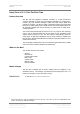
dCS 954 User Manual dCS Ltd Manual for Standard Software Version 1.5x June 2000 Tone (Tone Generator). This controls an internal Tone Generator, whose level and frequency can be adjusted. Pressing Set enters a submenu, which accesses the following functions: Level Freq On/Off Up The output level in dB0. It can be changed in 0.1dB steps using the Up and Down buttons. Press Set to accept the change. The rate of change accelerates if the button is held down. The range is from 0dB0 to –120dB0.
dCS 954 User Manual dCS Ltd Manual for Standard Software Version 1.5x June 2000 Figure 5 – In-phase Sys waveform Referring to Figure 5, if the triangular sections point up, that channel is in phase. A triangular section pointing up with a rectangular block on its left side indicates left channel. A rectangular block on the right indicates right channel. Figure 6 shows the waveforms with both channels inverted.
dCS 954 User Manual dCS Ltd Manual for Standard Software Version 1.5x June 2000 I-For (Input Format). Sets the AES input multi-wire format Input Format. There are 4 options: Auto US[1] US[2] US[4] The message flags on the selected input are checked and the format is automatically set to Single, Dual or Quad AES. Dual AES must be connected to AES 1 & 2 or AES 3 & 4. User-selected Single AES mode. User-selected Dual AES mode. User selected Quad AES mode.
dCS 954 User Manual dCS Ltd Manual for Standard Software Version 1.5x June 2000 BNC (BNC Button). In PCM mode, this controls the operation of the BNC button. Input RefCl Configures the BNC input connectors as a data input. Press the BNC button to select it. Configures the BNC word clock in (Clk In) connector as a reference clock input. Press the BNC button to sync the unit to the Word clock while taking data from one or more of the AES inputs.
dCS 954 User Manual dCS Ltd Manual for Standard Software Version 1.5x June 2000 S-No The control board serial number scrolls along the display. You will need something to write this on, if you call us for help. Flip (Flip channels). Normally set to Off. If you find the Left and Right outputs from your system are reversed due to a connection error, set Flip to On to digitally swap them back. The main display shows Flip.d while this feature is turned on.
dCS 954 User Manual dCS Ltd Manual part no: DOC136954 iss 2B1 Contact dCS on + 44 1799 531 999 (inside the UK replace + 44 with 0) Manual for Standard Software Version 1.5x June 2000 Page 29 file 135954ma2b1.pdf available from website email to: more@dcsltd.co.uk web site: www.dcsltd.co.
dCS 954 User Manual dCS Ltd Manual for Standard Software Version 1.
dCS 954 User Manual dCS Ltd Manual for Standard Software Version 1.5x June 2000 Replaying DSD from an 8 track 16/44.1 PCM Recorder 4-wire DSD from an 8 track 16 bit 44.
dCS 954 User Manual dCS Ltd Manual for Standard Software Version 1.
dCS 954 User Manual dCS Ltd Manual for Standard Software Version 1.5x June 2000 Replaying 6 channel DSD from a 24 track 16/44.
dCS 954 User Manual dCS Ltd Manual for Standard Software Version 1.
dCS 954 User Manual dCS Ltd Manual for Standard Software Version 1.5x June 2000 Upsampling a CD AES REF DIGITAL OUT PUSH WORDCLOCK IN L Hand Crafted by The Red Hot CD Player Co. R 16bit / 44.1kS/s dCS 992 AES 3 AES 4 1 Wordclock Outputs AES 2 AES/EBU Outputs more@dcsltd.co.uk AES 1 2 7 3 8 4 9 5 10 6 11 In External Sync 12 Loop Out Mains Fuse (2AT) On Off Remote 44.
dCS 954 User Manual dCS Ltd Manual for Standard Software Version 1.5x June 2000 Converting Quad AES to Single AES Quad AES 192kS/s CH1(L) CH2(R) Sensitivity d C S 954 Reference In Reference Out PUSH AES1 PUSH AES2 AES3 AES4 PUSH PUSH PUSH CH1 CH1(L) CH2(R) In Analogue CH2 In MAINS FUSE 2A(T) ON OFF SDIF-2/DSD Remote Out Out 75R Clk Digital I/O Single AES 96kS/s Figure 15 – Converting Quad AES to Double speed Single AES Select Quad AES and set the Ref In menu item to ddC.
dCS 954 User Manual dCS Ltd Manual for Standard Software Version 1.
dCS 954 User Manual dCS Ltd Manual for Standard Software Version 1.5x June 2000 dCS 954 TECHNICAL INFORMATION Anti Image Filtering The dCS 954 offers a choice of 4 anti-image filters on most sample rates. These filters affect the ultrasonic part of the spectrum - 20 kHz upwards. The unit is a DAC, with an output data rate set by the interface standard used.
dCS 954 User Manual dCS Ltd Manual for Standard Software Version 1.5x June 2000 Clocking The sample clock quality significantly determines the performance of a DAC. The highest quality clocks that are available are crystals, so we use these. The dCS 954 uses one of two on-board voltage controlled crystal oscillators (VCXOs) as a clock source – one for 48 kS/s related outputs and one for 44.1 kS/s related outputs.
dCS 954 User Manual dCS Ltd Manual for Standard Software Version 1.5x June 2000 DSD DSD is a single bit very high sample rate (2.822 MS/s) format, where the single bit words are heavily noise shaped to push noise energy above the audio band. The frequency response is very high (well above 100kHz) although at these high frequencies, much noise is also present. The SACD format sets 0 dB0DSD to be 6 dB below the peak to peak level one might expect a full scale sinewave to occupy.
dCS 954 User Manual dCS Ltd Manual for Standard Software Version 1.5x June 2000 Sample Alignment The dCS 954 aligns samples such that Word Clock Out aligns with AES3 samples out (Reference Out), the rising edge of Word Clock Out aligning with the start of the first illegal code in the X,Z subframe preamble and the falling edge aligning with the start of the Y subframe preamble. Figure 19 – Word Clock and AES3 outputs, 96 kS/s Figure 20 – Word Clock and AES3 outputs, 44.
dCS 954 User Manual dCS Ltd Manual for Standard Software Version 1.5x June 2000 When Word Clock In is used as a sync source, in and out are related as below. The lower waveform is the output, the upper one is the input. The misalignment is less than about 40ns. The scope shots below were taken with the unit sync’d to Word Clock In. Figure 21 – Word Clock In to Word Clock Out, 96 kS/s Figure 22 – Word Clock in to Word Clock Out, 44.
dCS 954 User Manual dCS Ltd Manual for Standard Software Version 1.5x June 2000 AES3 in and out (Reference Out) are related as below, where they are at the same sample rate, and the AES3 input is used as a sync source. The alignment is better than 40ns. Input is at the top of the displays, output is at the bottom. Signals are at the sockets on the dCS 954, the unit was slaved to AES1 and the Ref In menu item was set to Route.
dCS 954 User Manual dCS Ltd Manual for Standard Software Version 1.5x June 2000 Figure 24 – AES3 in to AES3 out, 44.1 kS/s AES3 Reference Out is also related to the phase of Clk In. The scope shots below were taken with the unit sync’d to Clk In Figure 25 – Word Clock In to AES3 Reference Out, 96 kS/s Figure 26 – Word Clock in to AES3 Reference Out, 44.1 kS/s Manual part no: DOC136954 iss 2B1 Contact dCS on + 44 1799 531 999 (inside the UK replace + 44 with 0) Page 44 file 135954ma2b1.
dCS 954 User Manual dCS Ltd Manual for Standard Software Version 1.
dCS 954 User Manual dCS Ltd Manual for Standard Software Version 1.
dCS 954 User Manual dCS Ltd Manual for Standard Software Version 1.5x June 2000 Frequency Response The overall frequency response is determined by the sample rate, the digital filter and the analogue filter. If imaging is to be avoided, all filters must cut-off before Fs/2 is reached, with a margin to allow for sufficient attenuation to be reached to effectively eliminate Nyquist images. At a sample rate of 44.
dCS 954 User Manual dCS Ltd Manual for Standard Software Version 1.5x June 2000 Group Delay The group delay for a dCS 904 and dCS 954 ADC and DAC were measured, at different sample rates. The results were as below (they are valid for software up to 1.5x): 32kS/s 44.1kS/s 48kS/s 88.2kS/s 96kS/s 176.
dCS 954 User Manual dCS Ltd Manual for Standard Software Version 1.5x June 2000 AES3 (AES/EBU) Format Message Handling - The AES/EBU interface decodes a data structure that conforms to the dCS version of AES3-1992. This contains 28 bits of Manchester encoded data, and a 4 bit near-Manchester encoded preamble in a subframe, and subframes are further assembled in a block and frame structure.
dCS 954 User Manual dCS Ltd Manual for Standard Software Version 1.5x June 2000 Figure 28 – AES3 format at 48 kS/s over 16 metres Manual part no: DOC136954 iss 2B1 Contact dCS on + 44 1799 531 999 (inside the UK replace + 44 with 0) Page 50 file 135954ma2b1.pdf available from website email to: more@dcsltd.co.uk web site: www.dcsltd.co.
dCS 954 User Manual dCS Ltd Manual for Standard Software Version 1.5x June 2000 Figure 29 – AES3 format at 48 kS/s over 94 metres Figure 30 – AES3 format at 96 kS/s over 16 metres Figure 31 – AES3 format at 96 kS/s over 94 metres Manual part no: DOC136954 iss 2B1 Contact dCS on + 44 1799 531 999 (inside the UK replace + 44 with 0) Page 51 file 135954ma2b1.pdf available from website email to: more@dcsltd.co.uk web site: www.dcsltd.co.
dCS 954 User Manual dCS Ltd Manual for Standard Software Version 1.5x June 2000 SDIF-2 PCM Format The SDIF-2 interface is a 4 wire NRZ interface - so the DC level on each signal line may not be constant. It contains 20 bits of audio data and has a block structure of 256 stereo samples, rather than the 192 of AES/EBU. There are 8 bits of message per channel per sample - with a further 3 bits being used for an "illegal code" based sync code.
dCS 954 User Manual dCS Ltd Manual for Standard Software Version 1.5x June 2000 Figure 32 – SDIF-2 PCM format at 96 kS/s Figure 33 – SDIF-2 PCM format at 44.1 kS/s SDIF-2 Messaging - The SDIF-2 message details are defined in the table following. DESCRIPTION Undefined Emphasis No emphasis Emphasis (15µsec, 50µsec) Dubbing Prohibit Dubbing allowed Dubbing inhibited Block Code Start of block Not start of block Definition 0000 0xxx xxxx x00x xxxx x01x xxxx xxx0 xxxx xxx1 xxxx xxxx 1... xxxx xxxx 0...
dCS 954 User Manual dCS Ltd Manual for Standard Software Version 1.5x June 2000 DSD on SDIF-2 An SDIF-2 interface can be used for DSD. The waveforms appear quite different to PCM format. However, they do produce transitions where the illegal code transitions were, and for this reason we advise against locking to the illegal transitions in SDIF-2. We recommend always using Word Clock with SDIF-2 signalling.
dCS 954 User Manual dCS Ltd Manual for Standard Software Version 1.5x June 2000 P3D Behaviour Mute on CRC Error The P3D format includes error checking. Data is packed into AES3 subframes, and each subframe is checked for integrity before it is converted to analogue. In the event of an error being detected in a subframe, the unit mutes the entire subframe, and passes control over to a more complex control mechanism. This looks for a long run of error free subframes before it unmutes – v1.
dCS 954 User Manual dCS Ltd Manual for Standard Software Version 1.5x June 2000 RS-232 Remote Control Interface Overall Description - dCS 9xx units can be controlled using a simple serial protocol, via the RS-232 ports, using the control format described below. All commands available from the front panel (and a few others, dCS use only) of a unit can be remotely controlled using this approach.
dCS 954 User Manual dCS Ltd Manual for Standard Software Version 1.5x June 2000 Transmit Message - The system employs the following protocol - all transactions are initiated by the PC. The PC is the transmitter and units on the daisy chain are receivers. Byte 1 : ID of unit to process command Byte 2 : Command (single byte) Byte 3 : Length of parameter string Byte 4 : List of parameters . .
dCS 954 User Manual dCS Ltd Manual for Standard Software Version 1.5x June 2000 The checksum is the sum of the bytes in the parameter list (bytes 5 to (last-1) byte) modulo 256. The minimum length of an acknowledge message is 1 byte, maximum 64. If the checksum is incorrect the transmitter should re-issue the command.
dCS 954 User Manual dCS Ltd Manual for Standard Software Version 1.5x June 2000 Command Streams - Example – a system of 9 units with ID’s set up as noted: 1 4 4 Master Clock (ID 1), P3D compatible ADCs (ID 2, 3, 4 and 5), P3D compatible DACs (ID 6, 7, 8 and 9). RS232 operating at 1200 baud. It is assumed that the transmitter operates on a round robin polling scheme and that each step completes before the next allowing for time outs.
dCS 954 User Manual dCS Ltd Manual for Standard Software Version 1.
dCS 954 User Manual dCS Ltd Manual for Standard Software Version 1.5x June 2000 Transmit -> [1][REQUEST_FS], request actual frequency Responds -> [ACK immediate][1], actual frequency The system is now set up with the Master Clock configured for 96k operation and the ADCs and DACs locked in PCM mode to 96k. Example: Switching to P3D - Change the Master Clock frequency to 44.1k prior to changing the ADC and DAC operating mode to DSD. Change the DAC operating mode prior to the ADC.
dCS 954 User Manual dCS Ltd Manual for Standard Software Version 1.5x June 2000 Transmit -> [8][REQUEST_DSD_MODE] Response -> [ACK immediate][8], actual mode Transmit -> [9][REQUEST_DSD_MODE] Response -> [ACK immediate][9], actual mode 11) Check ADCs for mode change. This command allows the Transmitter to check the mode of the ADCs. If a unit has not changed the transmitter should go back to step 9 and repeat the command.
RS_AUTO_SLAVE RS_MASTERSLAVE RS_ENABLE_DEBUG RS_SEL_FS RS_FILTER RS_EMPH 33 34 1 1 RS_OUT_MODE 36 1 RS_TRUNC RS_SNS 39 40 1 1 RS_DDC 41 1 RS_OUT_RATE 42 1 RS_MUTE 43 1 RS_AUTO 44 1 RS_7SEGS RS_INP_FORMAT 47 48 1 1 RS_4WIRE 49 1 RS_FLIP 50 1 RS_ACUT RS_FINE_LOCK_MODE 51 52 1 1 RS_WAVETYPE 63 1 RS_AMP RS_FREQ 64 65 1 1 Manual part no: DOC136954 iss 2B1 Contact dCS on + 44 1799 531 999 (inside the UK replace + 44 with 0) 0 X 0 X None Echos message Select Filter, 0-
RS_REF_MODES RS_OVLD_LEV RS_VOL RS_PHASE RS_REF_MODE RS_DSD_MODE RS_BAUD_RATE REQUEST_DSD_MODE REQUEST_FREQUENCY 0 X X 0 0 0 X X X X X X 0 X X Echos X message X X None Yes Yes X X X MClk Parameters in Response DDC Parameters Command Number of Byte Parameters in Command first parameter is terminator (AES) 77 2 0 = unterminated 1 = terminated second is reference mode 1 = ref out is internal 0 = pass through Overload threshold, format X 87 1 Digital volume control, format X 111 1 Phase
dCS 954 User Manual dCS Ltd Manual for Standard Software Version 1.5x June 2000 Power Consumption The dCS 954 has a linear power supply, and so power consumption changes as the mains voltage changes. The internal regulation is comparatively efficient for a linear supply, so these changes are kept to a minimum. Power consumption is independent of mains voltage setting.
dCS 954 User Manual dCS Ltd Manual for Standard Software Version 1.5x June 2000 Operating Conditions The dCS 954 has no ventilation slots or fan cooling. It dissipates relatively low power, so that usually allowing natural convection provides enough cooling in most circumstances. It is sensible, however, to not install the unit near heat sources such as radiators, hot air ducts or in direct strong sunlight.
dCS 954 User Manual dCS Ltd Manual part no: DOC136954 iss 2B1 Contact dCS on + 44 1799 531 999 (inside the UK replace + 44 with 0) Manual for Standard Software Version 1.5x June 2000 Page 67 file 135954ma2b1.pdf available from website email to: more@dcsltd.co.uk web site: www.dcsltd.co.
dCS 954 User Manual dCS Ltd Manual for Standard Software Version 1.5x June 2000 GENERAL TECHNICAL INFORMATION Jitter and PLL bandwidths Jitter and PLL performance are related. In a DAC, in many applications the clock for the received data has to be extracted from the signal coming into it. To do this, the DAC has to have circuitry that looks at data edges (edges are the only things that carry time information), and has to extract enough information from these to generate an stable internal clock.
dCS 954 User Manual dCS Ltd Manual for Standard Software Version 1.5x June 2000 the FIFO has to be significantly filled at all times, which is the same a delay in the signal path. A bit error rate measurement based on this approach has shown rates with an -14 upper bound of 5*10 . Manual part no: DOC136954 iss 2B1 Contact dCS on + 44 1799 531 999 (inside the UK replace + 44 with 0) Page 69 file 135954ma2b1.pdf available from website email to: more@dcsltd.co.uk web site: www.dcsltd.co.
dCS 954 User Manual dCS Ltd Manual for Standard Software Version 1.5x June 2000 OPTIONS Mains Voltage We ship with the mains wired according to the destination. The voltage option should be specified when the unit is ordered, by specifying the country of use. It can be updated later by your dealer, if necessary. Video Frequency VCXOs We can fit additional video frequency VCXOs (enabling frequencies such as 44.056kS/s and 47.952kS/s). These are best fitted at dCS, to allow full checking.
dCS 954 User Manual dCS Ltd Manual part no: DOC136954 iss 2B1 Contact dCS on + 44 1799 531 999 (inside the UK replace + 44 with 0) Manual for Standard Software Version 1.5x June 2000 Page 71 file 135954ma2b1.pdf available from website email to: more@dcsltd.co.uk web site: www.dcsltd.co.
dCS 954 User Manual dCS Ltd Manual for Standard Software Version 1.5x June 2000 MAINTENANCE AND SUPPORT Hardware Service & Maintenance dCS audio products are designed not to need regular maintenance, and contain no user serviceable parts: • • • • • there are no moving parts, there are no short life or wear-out parts used, the units have no holes through which liquids or contamination can normally enter, no dust deposits build up to degrade performance.
dCS 954 User Manual dCS Ltd Manual for Standard Software Version 1.5x June 2000 Software Installing New Software Updated operating software can be downloaded via the RS-232 link from a PC comm. port, using the Windows Remote software running on the PC, or can be copied from an EPROM installed internally. Using the RS-232 download is hands free, but takes about 40 mins per unit.
dCS 954 User Manual dCS Ltd Manual for Standard Software Version 1.5x June 2000 Hardware Update or Calibration You may wish to have your unit updated occasionally. dCS offer this service we will install any modifications or hardware updates that have occurred since your unit was first shipped, and give the unit a full retest to current standards, including re-calibrating its VCXOs (which drift over time). The price will depend on the hardware changes necessary – so contact your dealer or us.
dCS 954 User Manual dCS Ltd Manual part no: DOC136954 iss 2B1 Contact dCS on + 44 1799 531 999 (inside the UK replace + 44 with 0) Manual for Standard Software Version 1.5x June 2000 Page 75 file 135954ma2b1.pdf available from website email to: more@dcsltd.co.uk web site: www.dcsltd.co.
dCS 954 User Manual dCS Ltd Manual for Standard Software Version 1.5x June 2000 TROUBLESHOOTING Error Codes and Messages The error codes and messages reported by dCS 954 provide an effective means to diagnose the majority of problems that may be encountered in use - including problems with the overall system the unit operates in, internal device warnings and internal device failures. Please note that through damage or component failure, the unit self check may fail to operate.
dCS 954 User Manual dCS Ltd Manual for Standard Software Version 1.5x June 2000 System Messages and Error Codes Some other messages may be displayed that give indications of errors from other sources (outside the unit): Display Description n.Aud The data has been flagged by an AES3 message as Non Audio (perhaps a CD ROM). This message may also be displayed briefly when the sample rate is changed (see page 22) The unit is overheating, and performance may suffer.
dCS 954 User Manual dCS Ltd Manual for Standard Software Version 1.5x June 2000 The unit fails to respond to the controls • • • While locking to a source or changing some settings (e.g. Filter), the microcontroller inside the unit is busy and will not respond to new commands for a few seconds. Turning DSD mode on and off occupies the microcontroller for about 15 seconds. Short mains supply drop-outs may cause the microcontroller to lock up. Switch off the unit, wait 10 seconds then switch on again.
dCS 954 User Manual dCS Ltd Manual for Standard Software Version 1.5x June 2000 The output is monophonic • • • - If the unit is locked to one wire of Dual AES or Quad AES, the left channel signal will appear on both channels. Select the correct inputs. The source may actually be monophonic. Check that the signal is not mono’ed elsewhere in the system. Clicks or crackles occur on the outputs • • • • - Check that all cables are of a suitable type, connected correctly and not damaged.
dCS 954 User Manual dCS Ltd Manual for Standard Software Version 1.5x June 2000 dCS SUPPORT I wish .... If you wish your unit did something it does not, or that this manual told you something it does not, or that we made something we currently do not - tell us. If we can fix it with software, or a manual reprint, and we do so - we will update your unit free of charge. If we do decide to make the thing, we will discuss with you how you would like it to operate.
dCS 954 User Manual dCS Ltd Manual for Standard Software Version 1.5x June 2000 INDEXES AND SOFTWARE VERSION NUMBERS This manual is for standard software version 1.5x and P3D unit software v1.36. v1.5x differs from earlier standard software v1.3x and P3D software pre 1.36 in having a more friendly menu structure, with readback on current settings without having to change the settings, and supporting SDIF-3 for DSD.
dCS 954 User Manual dCS Ltd Manual for Standard Software Version 1.5x June 2000 Full Contents Product Features ................................................................................................3 Formats Syncing Functions Test Generator Ease of Use - 3 3 3 3 3 CONTENTS ..........................................................................................................4 About this Manual 5 Using Your dCS 954 For The First Time ........................................................
dCS 954 User Manual dCS Ltd Manual for Standard Software Version 1.5x June 2000 Phone Facs Part S-No Flip Loc End - 27 27 27 28 28 28 28 Typical Applications.........................................................................................30 Using a dCS 954 for DSD Using a Master Clock to Sync a dCS 954 Replaying DSD from an 8 track 16/44.1 PCM Recorder Operating Several Units on One Remote Chain Six Channel PCM Set Up Replaying 6 channel DSD from a 24 track 16/44.
dCS 954 User Manual dCS Ltd Manual for Standard Software Version 1.5x June 2000 Hardware Service & Maintenance User Changeable Parts Software Installing New Software During An Update … Hardware Update or Calibration Warranty Safety and Electrical Safety 72 72 72 73 73 73 74 74 74 TroubleShooting ...............................................................................................
dCS 954 User Manual dCS Ltd Manual for Standard Software Version 1.5x June 2000 Tables Table 1 – Phase LEDs and Channel Phasing ....................................................14 Table 2 – Emphasis Indication, low sample rates ..............................................15 Table 3 – Output Data format indication, higher sample rates ...........................15 Table 4 – AES/EBU i/o specifications.................................................................
dCS 954 User Manual dCS Ltd Manual for Standard Software Version 1.5x June 2000 Figures Figure 1 – Playing a CD........................................................................................8 Figure 2 – Rear Panel.........................................................................................10 Figure 3 – Front Panel ........................................................................................12 Figure 4 – Menu Sequence .........................................................
dCS 954 User Manual dCS Ltd Manual for Standard Software Version 1.5x June 2000 Keywords and Phrases 7 7-Seg .............................................................22 A A/B comparisons ...........................................27 Active input button .........................................13 Active input LED ............................................13 A-cut ..............................................................22 AES 1 button..................................................
dCS 954 User Manual dCS Ltd Manual for Standard Software Version 1.5x June 2000 LED, panel lock..............................................13 Lock failure ....................................................77 Lock, coarse ..................................................13 Lock, fine .......................................................13 Locking front panel ..................................13, 28 lockout ...........................................................28 M Maintenance .................
dCS 954 User Manual dCS Ltd Manual for Standard Software Version 1.5x June 2000 W Warranty ..............................................5, 70, 74 Manual part no: DOC136954 iss 2B1 Contact dCS on + 44 1799 531 999 (inside the UK replace + 44 with 0) Web site ........................................................ 80 Word Clock ........................... 11, 16, 27, 41, 78 Word clock alignment, in to out..................... 42 Page 89 file 135954ma2b1.