THE PH3 PATIO HEATER Use and Care Guide Models: ■ ■ ■ ■ ■ ■ PHFS-DW-SS PHFS-DW-BK PHFS-DW-WT PHFS-DW-BL PHFS-DW-GN PHFS-DW-BZ
A Message To Our Customers We are glad you selected the PH3 by DCS. Because this appliance contains features not found on any other patio heater, we recommend that you read this entire booklet before your first use. Keep it in a handy place as it has answers to questions that may occur during future use. Feel free to contact us if we can help you. When you write please include the model number of the heater. We thank you for buying the patio heater Made in America and wish you many years of enjoyment.
Table Of Contents SAFETY PRACTICES AND PRECAUTIONS ......................................................................3 FEATURES ...............................................................................................................................................4 ASSEMBLY TOOL & FASTENERS .............................................................................................4 ASSEMBLY INSTRUCTIONS ...........................................................................................
Safety Practices & Precautions • Read and become familiar with the entire manual. • Do not use in an explosive atmosphere, keep heater away from areas where gasoline or other flammable liquids or vapors are stored or used. • Before each use check for damaged parts such as hoses, regulators, pilot or burner. • Do not attempt to alter unit in any manner, ie: shorten post length, bypass safety valve or operate heater without the reflector. • Heater must always be placed on a hard and level surface.
Features • Weatherproof • Uniform Heat Pattern • Durable Non-Slip Wheels • Piezo Spark Ignition • Heats (16’-20’) Diameter Area • Uses 5 Gallon 20 lbs.
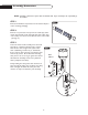
Assembly Instructions NOTE: Assembly of this heater requires basic mechanical skills. Proper assembly is the responsibility of the installer. STEP 1 FIG.01 Remove all individual components from all cartons. Dispose of the remaining packaging. STEP 2 Remove one protective end cap from the intake pipe, make certain pipe threads remain wrapped with white teflon tape. • Do not tape over the first two threads at the of the intake pipe (fig. 01) STEP 3 Locate the heater head assembly.
Assembly Instructions STEP 4 Remove the protective endcap at the bottom of the intake pipe. Make certain that the threads remain bare. Locate the reducer fitting and thread it onto the open end of the intake pipe. Hold the intake pipe above the threads with your channel lock pliers and tighten the reducer fitting clockwise onto the intake pipe. HARDWARE USED 1) P/N 18159 Reducer Fitting (1) FIG.
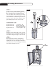
Assembly Instructions STEP 5 Locate the post assembly. Carefully insert the intake pipe through the top of the post assembly being careful not to allow the head assembly to slide too far down the post as undue scraping may occur. Align the screw holes on the panel of the burner head and the post assembly. Fasten the burner and post with the #10 screws. HARDWARE USED 1) P/N 15001-26 #10 Machine Screws (3) fig.
Assembly Instructions STEP 6 FIG.05 To join the post assembly with base cabinet you will need to place the base upright on the floor and lift the post assembly and place it onto the cabinet with the burner panel facing the same side as the door. Tighten the (8) nuts and bolts at the bottom of post assembly to the top of the cabinet base. Replace valve panel utilizing step 2 in the reverse order.
LP Gas Hook-Up The heater comes equipped with a regulator/hose assembly for connection to a standard 20 lb. / 5 gallon LP gas tank (not included) and 18” tank strap to secure the tank within the base. A dented or rusty LP tank may be hazardous and should be checked by your LP supplier. Never use an LP tank with a damaged valve. The LP tank must be arranged to provide for vapor withdrawal from the operating cylinder. Never connect an unregulated LP tank to the heater.
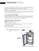
Gas Sounding Test PRECAUTIONS FIG.08 • Periodically check the whole gas system for leaks or immediately check if the smell of gas is detected. • Extinguish all open flames • Never leak test while smoking. If you can not stop a leak, turn off the cylinder valve and call the dealer you purchased the heater from or customer service 1-888-281-5698. 7 ORIFICE FITTING & SAFETY VALVE PILOT ASSEMBLY & PILOT TUBING 6 • Do not use heater until all connections have been leak tested and do not leak.
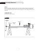
Assembly Instructions STEP 9 FIG.10 Locate the cap nuts, washers (4 ea.) and reflector shield.Tip the heater backwards and support it with stable horizontal surface (i.e. sawhorse, workbench step ladder). Install the reflector shield with the cap nuts and washers. Use caution not to over-tighten or damage the reflector. Return the unit to its upright position and continue to the next section for recommended locations and usage.
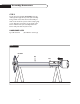
Locating Heater For Use This outdoor heater is primarily for temporary heating of outdoor patios, decks, spas, pool, and work areas. FIG.12 27” COMBUSTIBLES 19” MINIMUM This heater is not intended for indoor use or enclosed area use. Always ensure that adequate fresh air ventilation is provided. The minimum clearances to combustible construction shown here must be maintained at all times.
Lighting And Shutdown BEFORE TURNING THE GAS SUPPLY “ON” Visually inspect the hose assembly for evidence of excessive abrasion, cuts or wear. If the hose leaks it must be replaced prior to use. The replacement hose assembly shall be that specified by the manufacturer. Make sure the surrounding areas are free of combustible materials, gasoline and other flammable vapors or liquids. BEFORE LIGHTING For your safety, if relighting a hot heater, always wait 5 minutes.
Storage And Insect Warning NOTE: When storing the heater, the connection between the LP cylinder and the heater must be disconnected and the LP cylinder removed and stored outdoors in a well ventilated area. SPIDER & INSECT WARNING: Spiders or insects can nest in the burners or orifices of this or any outdoor gas appliance.This is a very dangerous condition which can damage the heater and render it unsafe for use.
Burner Removal And Installation NOTE: Unit must be cold before removal FIG.13 Emitter assembly BURNER REMOVAL 1) Remove reflector and emitter assembly by removing the screws that fasten the emitter assembly to the lower screen cone. 2) Remove valve panel; avoid tugging the ignition wire attached to backside of the valve panel at the igniter. 3) Remove the 1/4 NPT nut (using a 7/8 open end wrench) which holds the burner head to the orifice fitting. Remove the burner.
Pilot Cleaning When storing the heater the connection between the LP cylinder and the heater must be disconnected and the LP cylinder removed and stored outdoors in a well ventilated area. FIG.15 THERMOCOUPLE 1) Removing the valve panel to gain access to the pilot. (see figure 2 on page 5). 2) Remove the screw which fastens the pilot to the lower screen cone. PILOT 3) Hold the pilot with pliers, loosen and remove the nut at the base of the pilot.
Troubleshooting PROBLEM: Pilot does not light using the piezo lighter. Can you Match light the pilot? Piezo igniter problem. Is there a spark at the pilot when the piezo is pressed? YES See lighting instructions YES Is there adequate gas supply available? NO Remove valve panel, make sure igniter wire is attached to piezo igniter. Touch valve panel to safety valve cylinder to ground, and try again.
Troubleshooting PROBLEM: Is there adequate gas supply? Burner flame is low. NO Fill LP cylinder YES Is the supply hose bent or kinked? YES NO Straighten hose Check the burner and orifices for blockage, see page 15 PROBLEM: Emitter glow is uneven. Is the heater level? Is there adequate gas supply? YES Is the control knob in the full “on” position? (all the way counter clockwise)? Note: It is normal for the bottom 1/2” to 1” of the emitter not to glow.
Parts List ITEM PART NO. DESCRIPTION 1. 2. 2.b 3. 4. 5. 6. 7. 8. 9. 10. 11. 12. 13. 14. 15. 16. 17.
Parts List ITEM PART NO. DESCRIPTION 1. 2. 3. 4. 5. 6. 7. 8. 9. 10. 11. 12. 13. 23121-XX 23096-XX 23106-XX 17314 15003-15 15005-8 13230 18159 18290 23122 18143 23112 18023 Post Assembly (1) Base Assembly (1) Door (1) Manual (1) 1/4-20 Bolt (8) Nylon Washer (8) 900 Reg./Hose Assembly Reducer Fitting (1) Rubber Foot (4) Rubber Collar (1) 6” Wheel (2) Axle (1) Cap Nuts (2) 14. 15. 16. 17. 18. 19. 20. 21.
Service HOW TO OBTAIN SERVICE: For warranty service, contact DCS Customer Service at (888) 281-5698. Before you call, please have the following information ready: • Model Number • Serial Number • Date of installation • A brief description of the problem Your satisfaction is of the utmost importance to us.
Warranty LENGTH OF WARRANTY One (1) Year Full – Covers the entire product (excludes emitter screen). Five (5) Years Limited – Covers all stainless steel (components only, excludes emitter screen). DCS WILL PAY FOR: All parts found to be defective due to materials or workmanship, all repair labor and replacement parts covered one full year from date of purchase. Service must be provided by Authorized Factory Agent during normal working hours. DCS WILL NOT PAY FOR: • Installation, assembly or start-up.
Notes 23
Notes 24
CHAUFFERETTE DE PATIO PH3 Guide d’utilisation et d’entretien Modèles : ■ ■ ■ ■ ■ ■ PHFS-DW-SS PHFS-DW-BK PHFS-DW-WT PHFS-DW-BL PHFS-DW-GN PHFS-DW-BZ
À notre clientèle Nous sommes heureux que vous ayez choisi la chaufferette PH3 de DCS. Étant donné que cet appareil est doté de caractéristiques que l'on ne trouve pas dans d'autres chaufferettes de patio, nous vous recommandons de lire intégralement ce manuel avant la première utilisation. Gardez-le à portée de main car vous y trouverez des réponses à des questions susceptibles de surgir à l'avenir. N'hésitez pas à nous contacter si vous avez besoin d'aide.
Table des matières MESURES DE SECURITE ET DE PRECAUTION .........................................3 CARACTERISTIQUES..............................................................................4 OUTILS ET ATTACHES ...........................................................................4 INSTRUCTIONS DE MONTAGE.........................................................5-8 BRANCHEMENT DU GAZ ......................................................................9 ETANCHEITE ..................................
Mesures de sécurité et de précaution • Lisez ce manuel en entier afin de vous familiariser avec cet appareil. • N'utilisez pas la chaufferette dans une atmosphère explosive. Conservez-la loin des endroits où sont entreposés ou utilisés des liquides ou des produits aux vapeurs inflammables. • Avant chaque utilisation, inspectez l'appareil afin de détecter toute détérioration des tuyaux, du régulateur, du pilote ou du brûleur.
Caractéristiques • Toutes les pièces exposées à la chaleur intense sont fabriquées en acier inoxydable • Interruption automatique de l'alimentation en cas d'extinction • Base lestée stable / entretien minime • Accès facile, porte verrouillable • Grille radiante surdimensionnée en acier inoxydable • Peut être alimentée au gaz naturel • • • • • Résiste aux intempéries Dégage une chaleur uniforme Roues antidérapantes résistantes Allumage piézoélectrique Chauffe une aire d'un diamètre de 5 à 7 mètres (16 à 2
Instructions de montage REMARQUE : l'assemblage de cette chaufferette exige des connaissances de base en mécanique. L'installateur est responsable de l'assemblage adéquat. ETAPE 1 FIG.01 Sortez tous les éléments des cartons. Jetez l'emballage. ETAPE 2 Enlevez le capuchon protecteur d'un des bouts du tuyau d'admission. Recouvrez les filets de quelques tours de ruban de téflon. • N'entourez pas de ruban les deux premiers filets du tuyau (fig.
Instructions de montage ETAPE 4 Enlevez le capuchon qui recouvre l'extrémité inférieure du tuyau d'alimentation. Ne recouvrez pas les filets.Vissez d'abord à la main le réducteur au tuyau d'alimentation, en le faisant tourner dans le sens des aiguilles d'une montre. Serrez à fond le réducteur en tenant fermement le tuyau d'alimentation au moyen de la pince ajustable, en prenant soin de ne pas toucher aux filets. QUINCAILLERIE UTILISEE 1) Réf. 18159 Réducteur (1) FIG.
Instructions de montage ETAPE 5 Repérez le mât. Insérez soigneusement le tuyau d'alimentation au sommet du mât en évitant que la tête ne glisse trop bas sur le mât car cela pourrait l'égratigner. Alignez les trous de vis du boîtier du brûleur avec ceux du mât. Fixez le brûleur au mât à l'aide de vis de calibre 10. QUINCAILLERIE UTILISEE 1) Réf. 15001-26 Vis à métal cal. 10 (3) fig.
Instructions de montage FIG.05 ETAPE 6 Pour assembler le mât et la base de la chaufferette, posez celle-ci sur le plancher, soulevez le mât et mettez-le en place, en prenant soin d'orienter dans la même direction le panneau de commande du mât et la porte d'accès de la base. Fixez le mât à la base au moyen des 8 paires d'écrous et de boulons fournis. Replacez le panneau de commande en suivant, dans l'ordre inverse, les instructions données à l'étape 2. 2 1 3 QUINCAILLERIE UTILISEE 1) Réf.
Branchement du gaz La chaufferette comporte un tuyau souple et un régulateur pouvant s'adapter à un réservoir ordinaire (non inclus) contenant 20 livres ou 5 gallons de propane, ainsi qu'une courroie de 45 cm (18 po) servant à tenir en place le réservoir. Un réservoir bosselé ou rouillé peut constituer un danger. Faitesle examiner par votre fournisseur de gaz. N'utilisez jamais un réservoir de propane dont la soupape est endommagée.
Test d'étanchéité MESURES DE PRECAUTION FIG.08 • Inspectez de temps à autre la chaufferette pour voir s'il y a des fuites et sans tarder dès que vous détectez une odeur de gaz. • Éteignez toute flamme vive. • Ne fumez jamais lorsque vous vérifiez s'il y a des fuites. Si vous ne parvenez pas à arrêter une fuite, fermez la soupape du réservoir et téléphonez au détaillant chez qui vous avez acheté la chaufferette ou au service à la clientèle au : 1-(888)-281-5698.
Instructions de montage ETAPE 9 FIG.10 Ayez sous la main les écrous borgnes, les 4 rondelles et le réflecteur. Inclinez la chaufferette et appuyez-la sur un support stable (par exemple un tréteau, un établi ou un escabeau). Fixez le réflecteur au moyen des écrous borgnes et des rondelles. Ne serrez pas trop fort pour ne pas endommager le réflecteur. Remettez l'appareil sur sa base et lisez la section suivante pour connaître les dégagements à respecter lorsque vous l'utilisez.
Dégagement à respecter Cette chaufferette d'extérieur est principalement conçue pour le chauffage temporaire des patios, terrasses, bains tourbillons, piscines et chantiers en plein air. FIG.12 27 po MATERIAUX COMBUSTIBLES 19 PO AU MINIMUM N'utilisez pas cette chaufferette à l'intérieur ou dans un endroit fermé. Assurez-vous toujours que l'aération est suffisante. Respectez en tout temps le dégagement minimum recommandé ci-contre par rapport aux murs et aux matériaux combustibles.
Allumage et extinction AVANT D'OUVRIR L'ALIMENTATION EN GAZ : Procédez à l'inspection visuelle du tuyau souple afin d'y rechercher tout signe d'abrasion, de coupure ou d'usure excessive. Si le tuyau fuit, remplacez-le avant d'utiliser la chaufferette. Le tuyau de remplacement doit être conforme aux recommandations du fabricant. Assurez-vous qu'il n'y a pas de combustibles, d'essence, de vapeurs ou de liquides inflammables près de la chaufferette.
Entreposage et mise en garde relative aux insectes REMARQUE : avant d'entreposer la chaufferette, retirez-en le réservoir de propane. Remisez ce dernier à l'extérieur, dans un endroit bien aéré. MISE EN GARDE RELATIVE AUX ARAIGNEES ET AUX INSECTES : Les araignées ou les insectes peuvent faire leur nid dans le brûleur et les orifices de cet appareil ou de tout appareil au gaz remisé à l'extérieur.
Démontage et installation du brûleur REMARQUE : laissez refroidir le brûleur avant de le démonter. FIG.13 Grille radiante DEMONTAGE DU BRULEUR : 1) Pour démonter le réflecteur et la grille radiante, enlevez les vis qui retiennent la grille au cône qui se trouve en dessous. 2) Enlevez le panneau de commande. Évitez de tirer sur le fil d'allumage qui est relié à l'allumeur à l'arrière du panneau de commande.
Nettoyage du pilote Avant d'entreposer la chaufferette, retirez-en le réservoir de propane. Remisez ce dernier à l'extérieur, dans un endroit bien aéré. FIG.15 THERMOCOUPLE 1) Enlevez le panneau de commande pour accéder au pilote (voir la figure 2, page 5). 2) Retirez les vis qui retiennent le pilote au cône qui se trouve sous la grille radiante. PILOTE 3) Retirez l'écrou qui retient le pilote en tenant celui-ci au moyen d'une pince.
Résolution des problèmes PROBLÈME : L'allumeur piézoélectrique n'allume pas le pilote. Le pilote s'allume-t-il au moyen d'une allumette? Problème de l'allumeur. Y a-t-il une étincelle au pilote lorsque vous appuyez sur le bouton? OUI Voir les instructions relatives à l'allumage. OUI L'alimentation en gaz est-elle suffisante? NON Retirez le panneau de commande et assurezvous que le fil de l'allumeur est relié au dispositif d'allumage.
Résolution des problèmes PROBLÈME : L'alimentation en gaz est-elle suffisante? la flamme du brûleur est faible. NON Remplissez le réservoir. OUI Le tuyau d'alimentation est-il tordu? OUI NON Redressez le tuyau Vérifiez si le brûleur et les prises d'air ne sont pas bouchés, voir page 15 PROBLÈME : L'alimentation en gaz est-elle suffisante? le rayonnement de la grille radiante est inégal.
Pièces de rechange ARTICLE REF. DESCRIPTION 1. 2. 2.b 3. 4. 5. 6. 7. 8. 9. 10. 11. 12. 13. 14. 15. 15019-07 15005-10 15005-15 23002-SP 15021-09 23018-01 15003-15 15001-26 12015 23083 15077 15005-23 23024 15001-26 23064 16025-4 16. 17.
Pièces de rechange ARTICLE REF. DESCRIPTION 1. 2. 3. 4. 5. 6. 7. 23121-XX 23096-XX 23106-XX 17314 15003-15 15005-8 13230 8. 9. 10. 11. 12. 13. 18159 18290 23122 18143 23112 18023 Mât (1) Base (1) Porte (1) Manuel (1) Boulon 1/4-20 (8) Rondelle de nylon (8) Ensemble régulateur/tuyau souple à 90° Réducteur (1) Pied de caoutchouc (4) Collier de caoutchouc (1) Roue 6 po (2) Essieu (1) Écrous borgnes (2) 14. 15. 16. 17. 18. 19. 18024-03 23119 23108 15021-09 18201 23114 20. 21.
Service POUR L'OBTENTION DU SERVICE DE GARANTIE : Pour le service sous garantie, contactez le centre DCS agréé le plus proche au (888) 281-5698. Avant d'appeler, veuillez avoir les informations suivantes à portée de main : • • • • Numéro de modèle Numéro de série Date d'installation Brève description du problème Votre satisfaction revêt la plus haute importance pour nous.
Garantie DUREE DE LA GARANTIE Garantie complète d'un an. Couvre tout l'appareil (à l'exception de la grille radiante). Garantie limitée de cinq ans. Couvre tous les éléments en acier inoxydable (pièces seulement, à l'exception de la grille radiante). DCS COUVRE LES FRAIS SUIVANTS : Toutes les pièces défectueuses en raison d'un vice des matériaux ou de fabrication.
Notes 23
As product improvement is an ongoing process at DCS, we reserve the right to change specifications or design without notice. 5800 Skylab Road, Huntington Beach, CA 92647 Tel: (714) 372-7000 Fax: (714) 372-7001 Customer Service: (888) 281-5698 www.dcsappliances.com 5800 Skylab Road, Huntington Beach, CA 92647 Tél. : (714) 372-7000 Télécopieur : (714) 372-7001 Service à la clientèle : (888) 281-5698 www.dcsappliances.