
Installation guide
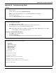

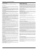

Appendix B: Troubleshooting Guide
Trouble Cause Troubleshooting
Trouble [2] AC Failure
No AC at panel AC input
terminals
Verify voltage measured across AC terminals is 16-18VAC. Replace
transformer if required.
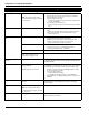
Trouble [3] Telephone Line Trouble
Phone Line Voltage at TIP, RING on
main panel less than 3VDC
• Measure the voltage across TIP and RING on the panel:
• No phone off-hook – 50VDC (approx)
• Any phone off-hook – 5VDC (approx)
• Wire incoming line directly to TIP and RING.
• If trouble clears, check wiring or the RJ-31 phone jack.
Trouble [4] Failure to Communicate
Panel fails to communicate one or more
events to central station
Connect a headset to TIP and RING of the control panel. Monitor for
the following conditions:
• Continuous dial tone
• Reverse TIP and RING
• Recorded operator message comes on
• Verify correct phone number is programmed
• Dial the number programmed using a regular telephone to
determine if a [9] must be dialed or if 800 service is blocked.
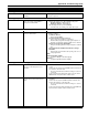
• Panel does not respond to handshakes.
• Verify the format programmed is supported by the central sta-
tion.
• Panel transmits data multiple times without receiving a
handshake
• Verify that the account number and reporting codes are cor-
rectly programmed.
NOTE:
Contact ID and Pulse formats
• Program a HEX [A] to transmit a digit [0]
SIA format
• Program a digit [0] to transmit a digit [0]
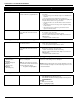
Trouble [5] Zone Fault Press [5] to determine specific zones with a fault trouble
Open circuit is present on one or more
fire zones on the main panel or zone
expander
• Ensure fire zones have a 5.6K resistor (Green, Blue, Red) con-
nected.
• Remove the wire leads from Z and COM terminals and measure
the resistance of the wire leads.
• An open circuit indicates a break in the wiring or resistor not
connected.
• Connect a 5.6K resistor (Green, Blue, Red) across the Z and
COM terminals. Verify the trouble condition clears.
An open circuit is present on PGM2
being used as a 2-wire smoke detector
input
• Ensure the correct 2.2K end-of-line resistor is connected (Red,
Red, Red).
• Remove the wire leads from PGM2 and AUX+ terminals and
measure the resistance of the wire leads.
• An open circuit indicates a break in the wiring or no resistor
connected.
• Connect a 2.2K resistor (Red, Red, Red) across the PGM2 and
AUX+ terminals. Verify the trouble condition clears.