
Owners Guide


8
INSTALLATION
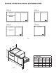
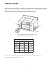
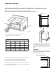
MAKE CUTOUT AND INSTALL SUPPORT STRUCTURE FLUSH INSTALLATION
1. Make a cut-out in your cabinet or island with the following dimensions:
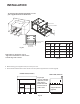
2. Place 3” X 4”s to provide support for the Access Drawers structure
in the locations indicated in the figure opposite (Fig. 4B).
3. Board lengths are provided in the table opposite (Fig. 5B).
Note: The frame should locate the Access Drawer assembly in the
center of the cutout, and be fastened to the enclosure such that the
unit is reliably secured in place.
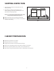
CUTOUT DIMENSIONS
Model
A
0,+1/8”
B
0,+1/8”
C D
ADR248 48 3/16” 221/16” 1.0” min. 1.0” min.
ADR236 36 3/16” 221/16” 1.0” min. 1.0” min.
ADR230 30 3/16” 221/16” 1.0” min. 1.0” min.
ADR224 24 3 /16” 221/16” 1.0” min. 1.0” min.
NOTE: Each corner of the cutout should be 90º for the Access Drawers to fit properly.
Fig. 3B
A
90º
B
Vent*
Vent*
Vent*
C
* Island installation to use minimum of 3 vents
providing 10 sq. in. per vent (typical).
90º
A
C
D
B
90º
A
C
D
B
A frame should be constructed 2” (51 mm)
setback from the front face of the product
to both push the product up against and
conceal the cutout clearance around the front
frame.
Important!
Do not seal the product in with silicone caulk or
similiar. Doing so will result in the product being
difficult to remove for servicing.
2 - 5/8” (67 mm)
D
Minimum 3/16” (4 mm) cutout
clearance around front frame