
Owners Guide


7
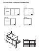
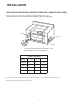
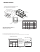
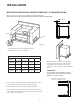
INSTALLATION
Fig. 5A
Fig. 4A
island cutout
1-1/2" Bottom of center divider to
C
B
A
A
B
E
D
2-5/8” 21-1/2" support
boards must
t in this area.
Sticker location of
Model, Serial, Code Number
*
SUPPORT BOARD DIMENSIONS
Model A B C D E
48” 2 X 20” 11/2”* 31/2” min. 14 12
36” 20” 11/2”* 31/2” min. 14
30” 2 X 20” 11/2”* 31/2” min. 14 12
24” 20” 11/2”* 31/2” min. 14
To ensure proper drawer operation, be sure
your support boards are flat & level.
*Dependent on application. Top of
support boards must be 1/2” above the
bottom edge of the cutout.
Fig. 6A
4. When installing your support boards, be sure they are level.
5. Ensure that the bottom of the center divider rests on top of the support boards as shown (Fig. 4A).
For proper
support & drawer
operation, insure
that support
boards are level
front to back &
side to side.
Support Board (typical)
Support Boards
(typical)
FRONT VIEW TYPICAL
END VIEW TYPICAL