
Operation Manual

GENERAL RULES
All servicing operations described in this section must be carried
out by qualified personnel only.
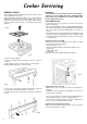
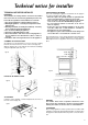
Before starting any servicing operations on a cooker, it must be
unplugged or switched off at the mains supply. If work is to be
carried out on the electrical or gas components underneath the
hob (e.g. switches, thermostat taps, etc.) follow the order shown
in Fig. 27
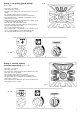
1) remove the pan supports
2) remove the burners and unscrew the screws as shown in
Fig. 27
3) unscrew the 7 screws on the back of the cooker (Fig. 28).
Having completed the above, remove the hob.
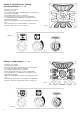
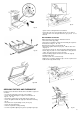
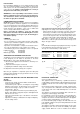
To remove the control panel, follow the instructions in Fig. 29,
removing knobs “A” and unscrewing the screws “B”.
To replace the hob and control panel, repeat the operation in
reverse.
IMPORTANT:
Check that the hose connecting the cooker to the gas pipe or
cylinder is in good condition and replace if damaged with a
pipe meeting correct standards, in accordance with B.S. 669.
Respect expiry dates for use.
REPLACEMENT PARTS
If, after many years of good service, it becomes necessary to
replace certain parts:
- Go to your SUPPLIER or contact our After Sales Department.
- Give them the details provided on the DATA PLATE; you will find
this on the inside of the Plate Warming Door (see Fig. 3 on
page 3).
- They will have the parts list and technical documentation rela-
ting to our products, and will quickly be able to supply you with
any replacement parts and arrange for any necessary repairs
to be carried out.
Replacement of the oven light
This light is located on the ceiling of the oven, and is accessible
from the inside of the oven (Fig. 30)
- Unscrew the glass cover
- Remove the light and replace with another with the same
specification:
- Voltage 230V 50Hz
- Power 25W
Base E27 - Resistant to high temperatures (300°C).
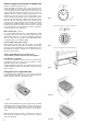
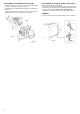
Replacement of the oven door
- With the door open, insert hook “A” into the moving part of
hinge “B”
- Partially close the door and force it upwards to remove stop “C”
and sector “B” of the hinge.
- As soon as the hinge is free, pull the door forwards tilting it sli-
ghtly upwards to release sectors “C” and “B” (Fig. 31).
- To reassemble, repeat the operations in reverse, taking care to
insert sectors “C” and “B” into their housing.
Replacing and cleaning the door glass
With the door dismantled, simply unscrew screws “A” from the
oven door lining. (Figs 32 - 32/A).
fig. 27
fig. 28
Cooker Ser
Cooker Ser
vicing
vicing
fig. 30
fig. 29
14