
Operation Manual
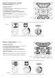
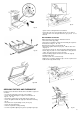

ADJUSTING THE LOW SETTINGS (REDUCED FLOW)
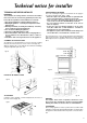
Adjusting the low settings of the hob burners (Fig. 45)
- light one burner at a time, in the fully on position, remove the
knob using a screwdriver, unscrew by approximately three
turns minimum screw H located on the right hand side of the
stem, turn the tap to the left to the reduced gas flow position
and turn screw H until a small regular flame is obtained.
With butane or propane gas the screw will be screwed fully
down. These screws are pierced and mounted on the tap accor-
ding to the type of burner.
N.B.
Check that when turning the tap rapidly from the fully on position
to the minimum position, the burner does not go out.
The taps are colour-marked (see table below):
ELECTRICAL CONNECTION
(varies according to model)
This appliance must be installed by a qualified electrician to
comply with the relevant Institute of Electrical Engeneers (I.E.E.)
regulations and also the local electricity supply company requi-
rements.
Check that the network characteristics (voltage, nominal power,
etc.) correspond to those indicated on the small plate mounted
on the inside of the oven or Plate Warming Door or on the back
of the cooker.
The appliance is designed for installation with connection to a
single phase earthed supply, 230V~50Hz.
For combination cookers (gas-electricity), see the following note.
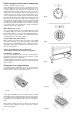
For direct connection to the network (cable without plug) an
omnipolar cutout device should be fitted upstream of the applian-
ce with a contact opening distance of at least 3mm.
For connection with a plug, fit a plug to the cable that meets cur-
rent standards suitable for the power rating indicated on the data
plate (Fig. 3, page 3).
The appliance should be earthed using particular care by a qua-
lified engineer, who can also check the suitability of the power
supply network. When the cooker is installed, check that the
18
fig. 45
LPG GAS ONLY
Do not install this appliance in a room below ground level. This
does not preclude installation in rooms which are basements
with respect to one side of the building but open to ground level
on the opposite side. Failure to install appliances correctly is
dangerous and could lead to prosecution.
WARNING: It is the responsibility of the installer to ensure
that the standards referred to below are strictly adhered to.
The manufacturer declines all responsibility deriving from
the failure to apply these standards.
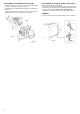
CONNECTION TO THE GAS MAINS
IMPORTANT: The installation must be carried out in compliance
with local regulations. Install the appliance in a well-ventilated
room, check that the gas meter capacity and pipe diameters are
sufficient to supply all the connected appliance. Do not forget to
install, upstream of the appliance, a gas cock no smaller than
1/2”, in a clearly visible and accessible position.
Before connecting the appliance, check the data plate
affixed to the inner side of the Plate Warming Door or to the
back of the appliance for the type of gas, the working pres-
sure and the capacity.
COMMENT:
- do not forget to fit the seal
- the soft or flexible hose must be visible along its entire length,
and must pass behind the appliance at floor level where the
supply comes from the opposite side.
- Important: once installation is complete, check that all connec-
tion seals are tight using a soapy solution, never a flame.
- check that the gas pressure entering the cooker is as required:
Liquid gas: butane G28/30mbar
propane G31/37mbar
Methane gas: natural G20/20mbar
ADAPTATION FOR DIFFERENT TYPES OF GAS
To adapt the cooker for a different type of gas than that for which
it was designed (see the labels on the inside of the Plate
Warming Door), carry out the following operations:
a) disconnect the appliance from the mains to avoid any acci-
dental contact.
b) replace the burner injectors on the hob:
c) adjusting the minimum settings of the hob burners
No adjustment of the burner primary air is required.
Once the gas regulation is completed, replace the data plate
inside the plate warming door (Fig. 3) with the correct one sup-
plied with the injector set.
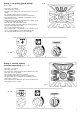
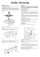
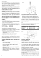
CHANGING THE INJECTORS FOR THE DIFFERENT TYPES
OF GAS
Hob Burners:
- remove the pan stands, the flame dividers and the burner
heads from their mountings;
- select from the pack of injectors, checking the corresponding
indication on the injector, the appropriate one for each burner
and for the desired type of gas (see “table of technical
characteristics”, page 3);
- using a 7 mm spanner unscrew the injectors fitted (Fig. 44)
Replace them with the appropriate injectors and tighten them
without excessive force;
- replace the heads and the caps of the burners on the burner
cap supports;
- adjust the low settings as indicated in the chapter “Adjusting
the low settings” below.
Rapid burner R diameter 0.42 mm yellow
Semi-rapid burner B diameter 0.32 mm blue
Auxiliary burner A diameter 0.27 mm red
Fish burner P diameter 0.57 mm white
Kwali burner BK diameter 0.57 mm white
fig. 44