Istruzioni per l'uso e l'installazione Directions for use and instructions for installation Notice d'utilisation et d'installation Gebrauchs- und Installationsanweisung Gebruiks- en installatie-aanwijzing Cappa decorativa Decorative hoods Hottes décoratives Wand-Dekorhauben Decoratieve wandkappen DHD498XE1
Gentile Signora, Caro Signore, Se seguirà con cura le raccomandazioni contenute in questo Libretto Istruzioni, la sua Cappa si manterrà efficiente nel tempo e le consentirà di ottenere costantemente le migliori prestazioni.
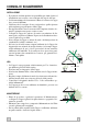
CONSIGLI E SUGGERIMENTI INSTALLAZIONE • Il produttore declina qualsiasi responsabilità per danni dovuti ad installazione non corretta o non conforme alle regole dell’arte. • La distanza minima di sicurezza tra il Piano di cottura e la Cappa deve essere di 650 mm. • Verificare che la tensione di rete corrisponda a quella riportata nella targhetta posta all’interno della Cappa. • Per Apparecchi in Classe Ia accertarsi che l’impianto elettrico domestico garantisca un corretto scarico a terra.
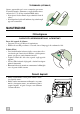
CARATTERISTICHE Ingombro Componenti 12a 7.2.1 11 Rif. 1 2.1 2.2 8 9 15 16 2.1 12c 2.2 Q.tà Componenti di Prodotto 1 Corpo Cappa completo di: Comandi, Luce, Gruppo Ventilatore, Filtri 1 Camino Superiore (opzionale) 1 Camino Inferiore (opzionale) 1 Griglia direzionata Uscita Aria 1 Flangia (opzionale) 1 Angolare (opzionale) 1 Coperchio filtrante 12d Rif. Q.tà Componenti di Installazione 7.2.
INSTALLAZIONE 1÷2 Foratura Parete e Fissaggio Staffe X 7.2.1 200 200 11a 1 1 11 2 2 362 12a 960 180 180 Tracciare sulla Parete: • una linea Verticale fino al soffitto o al limite superiore, al centro della zona prevista per il montaggio della Cappa; • una linea Orizzontale a 960 mm min. sopra il Piano di Cottura. • Segnare un punto (1) sulla linea orizzontale a 200 mm alla destra della linea verticale di riferimento.
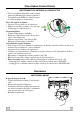
Montaggio Corpo Cappa • Aprire i pannelli aspiranti. • Sganciare il pannello dal corpo cappa facendo scorrere l’apposita leva del perno di fissaggio.(A) • Togliere i Filtri Antigrasso agendo sulle apposite maniglie. • Regolare le due viti Vr, delle staffe 11a, ad inizio corsa.(B) • Agganciare il corpo cappa alle 2 staffe 11a. • Dall’interno del corpo cappa agire sulle Viti Vr per livellare il Corpo Cappa. Vr • Avvitare la vite di sicurezza 11.
Montaggio Camino Il camino può essere installato solo con la cappa collegata in versione aspirante. • Fissare l’angolare 15 al corpo cappa con le viti 12d (2,9 x 9,5) in dotazione. Camino superiore • Allargare leggermente le due falde laterali, agganciarle dietro le Staffe 7.2.1 e richiuderle fino a battuta. • Fissare lateralmente alle Staffe con 4 Viti 12c (2,9 x 6,5) in dotazione.
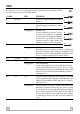
USO La cappa può essere accesa direttamente alla velocità desiderata, premendo il relativo tasto senza passare per il tasto 0/1 motore. TASTO L LED 0/1 Luce T1 0/1 Motore acceso Lampeggiante T2 Velocità acceso Lampeggiante T3 T4 Velocità Velocità acceso Fisso Lampeggiante S1 Led Fisso Lampeggiante IT L FUNZIONI Accende e spegne l’Impianto di IllumiT1 nazione. Prima velocità. Spegne la cappa se premuto per circa T2 2”. Ricambio 24h Si attiva premendo per circa 5” il tasto.
TELECOMANDO (OPZIONALE) Questo apparecchio può essere comandato per mezzo di un telecomando, alimentato con pile alcaline zincocarbone da 1,5 V del tipo standard LR03-AAA. • Non riporre il telecomando in prossimità di fonti di calore. • Non disperdere le pile nell’ambiente, depositarle negli appositi contenitori. MANUTENZIONE Filtri antigrasso PULIZIA FILTRI ANTIGRASSO METALLICI AUTOPORTANTI Reset del segnale di allarme • Spegnere le Luci e il Motore di aspirazione.
Filtro antiodore (Versione Filtrante) SOSTITUZIONE FILTRO ANTIODORE AL CARBONE ATTIVO • Non sono lavabili nè rigenerabile, vanno sostituiti quando il led S1 lampeggia o almeno ogni 4 mesi. La segnalazione di Allarme si verifica solo quando è azionato il Motore di aspirazione. Reset del segnale di allarme • Spegnere le Luci e il Motore di aspirazione. • Premere il tasto T3 per almeno 3 secondi, sino al lampeggio di conferma dei led. B A Sostituzione Filtro • Togliere i Filtri antigrasso metallici.
Dear Customer, If you follow the recommendations contained in this Instruction Manual, your appliance will give you constant high performance and will remain efficient for many years to come.
RECOMMENDATIONS AND SUGGESTIONS INSTALLATION • The manufacturer will not be held liable for any damages resulting from incorrect or improper installation. • The minimum safety distance between the cooker top and the extractor hood is 650 mm. • Check that the mains voltage corresponds to that indicated on the rating plate fixed to the inside of the hood. • For Class I appliances, check that the domestic power supply guarantees adequate earthing.
CHARACTERISTICS Dimensions Components 12a 7.2.1 11 Ref. 1 2.1 2.1 2.2 8 9 15 16 12c 2.2 Q.ty Product Components 1 Hood Body, complete with: Controls, Light, Blower, Filters 1 Upper Section (optional) 1 Lower Section (optional) 1 Directional Air Outlet grille 1 Flange (optional) 1 Angle iron (optional) 1 Filter cover 12d 15 Ref. Q.ty Installation Components 7.2.
INSTALLATION 1÷2 Wall drilling and bracket fixing X 7.2.1 200 200 11a 1 1 11 2 2 362 12a 960 180 180 On the wall, draw • a Vertical line up to the ceiling or upper limit, at the centre of the area in which the Hood is to be fitted; • a Horizontal line at a minimum of 960 mm above the Cooker Top. • Mark a point (1) on the horizontal line, 200 mm to the right of the vertical reference line. • Repeat this operation on the other side, checking that the two marks are level.
Mounting the hood body • Open the ducting panels. • Disconnect the panel from the hood canopy by sliding the fixing pin lever.(A) • Remove the metal grease filters by turning the handles provided. • Adjust the two screws Vr, on brackets 11a, to a minimum.(B) • Hook the hood canopy onto the two brackets 11a. • From inside the hood canopy, adjust the screws Vr to set the Hood Canopy level. Vr (B) • Tighten the safety screw 11.
Flue assembly The chimney can only be installed with exhausting hood • Fasten the angle iron 15 to the hood canopy using the screws 12d (2,9 x 9,5) provided. Upper exhaust flue • Slightly widen the two sides of the upper flue and hook them behind the brackets 7.2.1, making sure that they are well seated. • Secure the sides to the brackets using the 4 screws 12c (2,9 x 6,5) supplied.
USE Control Panel The hood can be switched on pushing directly onto the requested speed without firstly having to select 0/1 button. KEY L T1 LED 0/1 Light 0/1 Motor on FUNCTIONS Turns lighting on and off. First speed. When pressed for about 1 seconds the motor is switched off. Flashing T2 Speed on Flashing T3 T4 Speed Speed on Fixed Flashing S1 Led Fixed Flashing GB L T1 T2 24h Changeover This is enabled by pressing and holding the button for approximately 5".
REMOTE CONTROL (OPTIONAL) The appliance can be controlled using a remote control powered by a 1.5 V carbon-zinc alkaline batteries of the standard LR03-AAA type. • Do not place the remote control near to heat sources. • Used batteries must be disposed of in the proper manner. MAINTENANCE Grease filters CLEANING METAL SELF- SUPPORTING GREASE FILTERS Alarm signal reset • Switch off the lights and extractor motor. • Press button T3 for at least 3 seconds, until the leds start to flash.
Activated charcoal filter (Recirculation version) REPLACING THE ACTIVATED CHARCOAL FILTER • The filter is not washable and cannot be regenerated. It must be replaced when led S1 flashes or at least every 4 months. The alarm signal will only light up when the extractor motor is switched on. Alarm signal reset • Switch off the lights and extractor motor. • Press button T3 for at least 3 seconds, until the leds start to flash.
Chère Madame, Cher Monsieur, Si vous suivez attentivement les recommandations contenues dans ce mode d’emploi, votre hotte restera toujours efficace, et fournira constamment les mêmes performances.
CONSEILS ET SUGGESTIONS INSTALLATION • Le fabricant décline toute responsabilité en cas de dommage dû à une installation non correcte ou non conforme aux règles de l’art. • La distance minimale de sécurité entre le plan de cuisson et la hotte doit être de 650 mm au moins. • Vérifier que la tension du secteur correspond à la valeur qui figure sur la plaquette apposée à l’intérieur de la hotte.
CARACTERISTIQUES Encombrement Composants 12a 7.2.1 11 Réf. 1 2.1 2.1 2.2 8 9 15 16 12c 2.2 Q.té Composants de Produit 1 Corps Hotte équipé de:Comandes, Lumière,Groupe Ventilateur,Filtres 1 Cheminée Supérieure (si fournie) 1 Cheminée Inférieure (si fournie) 1 Grille orientée Sortie de l’Air 1 Flasque (si fournie) 1 Cornière (si fournie) 1 Couvercle filtrant 12d Réf. Q.té Composants pour l ’installation 7.2.
INSTALLATION 1÷2 Perçage Paroi et Fixation Brides X 7.2.1 200 200 11a 1 1 11 2 2 362 12a 960 180 180 Tracer sur la Paroi : • une ligne Verticale jusqu’au plafond ou à la limite supérieure, au centre de la zone prévue pour le montage de la Hotte ; • une ligne Horizontale à 960 mm. min. au-dessus des Plaques de Cuisson. • Marquer un point (1) sur la ligne horizontale à 200 mm. à droite de la ligne verticale de référence. • Répéter cette opération du côté opposé, en vérifiant le nivellement.
Montage Corps Hotte • Ouvrir les panneaux aspirants. • Décrocher le panneau du corps de la hotte, en faisant coulisser le levier du goujon de fixation spécialement prévu.(A) • Enlever les filtres Anti-graisse, en intervenant sur les poignées spécialement prévues. • Régler les deux vis Vr, des brides 11a, en début de course.(B) • Accrocher le corps de la hotte aux 2 brides 11a. • Depuis l’intérieur du corps de la hotte, intervenir sur les Vis Vr pour niveler le Corps de la Hotte.
Montage Cheminée La Cheminée peut être installée uniquement en version aspirante • Fixer la cornière 15 au corps de hotte avec le vis 12d (2,9 x 9,5) fournies. Cheminée supérieure • Elargir légèrement les deux bords latériaux, et les accrocher derrières les brides 7.2.1 ; refermer jusqu’à la butée. • Fixer latéralement aux brides à l’aide des 4 vis 12c fournies.
UTILISATION Tableau des commandes Il est possible d’allumer la hotte directement à la vitesse demandée en pressant la touche sans devoir d’abord utiliser la touche 0/1. TOUCHE LED FUNCTIONS L 0/1 éclairage Allume et éteint l'éclairage. T1 0/1 Moteur Allumé Première vitesse. Clignotement Cette touche permet d’éteindre la hotte en y pressant pour environ 1 secondes. T1 Changement 24h T2 On l'active en appuyant sur la touche pendant 5" environ. Cette fonction permet d'obtenir une aspiration de 100 m3/h.
TELECOMMANDE (FOURNIE SUR DEMANDE) Il est possible de commander cet appareil au moyen d’une télécommande, alimentée avec des piles alcalines zinccharbon 1,5 V du type standard LR03-AAA. • Ne pas ranger la télécommande à proximité de sources de chaleur. • Ne pas jeter les piles; il faut les déposer dans les récipients de récolte spécialement prévus à cet effet.
Filtre anti-odeur (Version filtrante) REMPLACEMENT FILTRE AU CHARBON ACTIF • Il n’est ni lavable ni régénérable, il faut donc le remplacer quand la del S1 clignote ou bien au moins tous les 4 mois. La signalisation d’Alarme a lieu uniquement lorsque le Moteur d’aspiration est actionné. Remise à l’état initial du signal d’alarme • Éteindre les Lumières et le Moteur d’aspiration. • Appuyer sur la touche T3 pendant 3 secondes au moins, jusqu’au clignotement de confirmation des dels.
Sehr geehrte Damen und Herren, bitte lesen Sie die Bedienungsanleitung aufmerksam durch, damit Sie alle Möglichkeiten und Vorteile Ihrer neuen Dunstabzugshaube voll nutzen können und über lange Zeit hin gute Leistungen erzielen.
EMPFEHLUNGEN UND HINWEISE MONTAGE • Der Hersteller haftet nicht für Schäden, die auf eine fehlerhafte und unsachgemäße Montage zurückzuführen sind. • Der minimale Sicherheitsabstand zwischen Kochmulde und Haube muss 650 mm betragen. • Prüfen, ob die Netzspannung mit dem Wert auf dem im Haubeninneren angebrachten Schild übereinstimmt. • Bei Geräten der Klasse I ist sicherzustellen, dass die elektrische Anlage des Wohnhauses über eine vorschriftsmäßige Erdung verfügt.
CHARAKTERISTIKEN Platzbedarf Komponenten 12a 7.2.1 11 2.1 12c 2.2 Pos. 1 St. 1 2.1 2.2 9 8 15 16 1 1 1 1 1 1 Produktkomponenten Haubenkörper mit Schaltern,Beleuchtung, Gebläsegruppe,Filter oberer Kaminteil (option) unterer Kaminteil (option) Flansch (option) Luftleitgitter Luftaustritt (option) Winkel (option) Filterdeckel 12d 15 Pos. 7.2.1 11 11a 12a 12c 12d 9 8 12d 12c 16 11a 1 St.
MONTAGE 1÷2 Bohren der Befestigungslöcher und Fixieren der Befestigungsbügel X 7.2.1 200 200 11a 1 1 11 2 2 362 12a 960 180 180 An der Wand: • eine vertikale Linie bis zur Decke oder oberen Begrenzung zeichnen, und zwar in der Mitte des Bereiches, der zur Montage der Haube vorgesehen ist; • eine horizontale Linie mindestens 960 mm oberhalb der Kochmulde zeichnen. • 200 mm rechts von der vertikalen Bezugslinie einen Punkt (1) auf der horizontalen Linie kennzeichnen.
Montage des Haubenkörpers • Die Filterpaneele öffnen. • Die Fettfilter mit den entsprechenden Griffen demontieren.(A) • Die Platte vom Haubenkörper aushaken, indem der Hebel des Befestigungsstiftes verschoben wird. • Die beiden Schrauben Vr der Bügel 11a so regulieren, dass sie nur bis zum Gewindebeginn eingeschraubt sind.(B) • Den Haubenkörper bei den 2 Bügeln 11a einhaken. • Vom Haubeninneren her den Haubenkörper mit Hilfe der Schrauben Vr ausrichten. Vr (B) • Die Sicherheitsschraube 11 festziehen.
Kaminmontage Der Kamin Kann nur bei der Haube in der Abluftausführung angebracht werden. • Das Winkelstück 15 am Lüftereil mit 5 der Lieferung beigefügten Schrauben 12d (2,9x9,5) befestigen. Oberer Kaminteil • Die beiden seitlichen Schenkel leicht auseinanderbiegen, hinter den Bügeln 7.2.1 einhängen und bis zum Anschlag wieder schließen. • Bei den Bügeln mit Hilfe der 4 mitgelieferten Schrauben 12c fixieren.
BEDIENUNG Bedienfeld Die Haube kann direkt auf die gewünschte Stufe eingeschaltet werden ohne daß man vorher auf die Gebläsetaste 0/1 drückt. TASTE LED FUNKTION L L 0/1 Beleuchtung Ein- und Ausschalten der Beleuchtung. T1 0/1 Motor Eingeschaltet Erste Geschwindigkeitsstufe. T1 Schaltet die Haube aus wenn die Taste für ungefähr 2’’ gedrückt wird Blinklicht Luftaustausch 24h T2 Wird durch cirka 5" dauerndes Drücken der Taste aktiviert.
FERNBEDIENUNG (OPTION) Dieses Gerät kann mit einer Fernbedienung gesteuert werden, welche mit alkalischen Zink-Kohle-Batterien 1,5 V des Standardtyps LR03-AAA versorgt wird. • Die Fernbedienung nicht in die Nähe von Hitzequellen legen. • Batterien müssen vorschriftsmäßig entsorgt werden. WARTUNG Fettfilter METALLFETTFILTER REINIGUNG Rücksetzen der Sättigungsanzeige • Licht und Gebläsemotor abschalten. • Mindestens 3 Sekunden lang die Taste T3 drükken, bis die Leds zur Bestätigung zu blinken beginnen.
Geruchsfilter (Umluftversion) AUSTAUSCHEN DER AKTIVKOHLE FILTER • Dieser Filter kann weder gewaschen noch wiederverwendet werden und ist bei Blinken der Led S1 oder zumindest alle 4 Monate auszutauschen. Die Sättigungsanzeige erfolgt nur bei laufendem Gebläsemotor. Rücksetzen der Sättigungsanzeige • Licht und Gebläsemotor abschalten. • Mindestens 3 Sekunden lang die Taste T3 drükken, bis die Leds zur Bestätigung zu blinken beginnen. B A Austauschen der Filter • Die Metallfettfilter entfernen.
Geachte mevrouw, meneer, Als u de in deze Gebruiksaanwijzing beschreven aanbevelingen zorgvuldig opvolgt, blijft uw kap steeds in goede staat en zal hij altijd optimale prestaties leveren.
ADVIEZEN EN SUGGESTIES INSTALLATIE • De fabrikant aanvaardt geen enkele aansprakelijkheid voor schade die voortkomt uit onjuiste of niet overeenkomstig de regels der kunst uitgevoerde installaties. • De minimale veiligheidsafstand tussen de kookplaat en de wasemkap bedraagt 650 mm. • Controleer of de netspanning correspondeert met de spanning die aangegeven is op het plaatje aan de binnenkant van de wasemkap.
EIGENSCHAPPEN Buitenafmetingen Onderdelen 12a 7.2.1 11 2.1 12c 2.2 Ref. 1 1 Productonderdelen Wasemkap compleet met:Bedieningen, Licht,Ventilatorgroep,Filters Bovenstuk (optie) Onderstuk (optie) Richtingrooster luchtuitlaat Reductieflens (optie) hoekstuk (optie) Filterdeksel 2.1 2.2 8 9 15 16 1 1 1 1 1 1 Ref. 7.2.
INSTALLATIE 1÷2 Boren van gaten in de wand en bevestiging van de draagbeugels X 7.2.1 200 200 11a 1 1 11 2 2 362 12a 960 180 180 Teken op de wand: • een verticale lijn tot het plafond of tot de bovenste limiet in het midden van de zone waar de afzuigkap moet worden gemonteerd; • een horizontale lijn op min. 960 mm afstand van het kookvlak. • Teken een punt (1) op de horizontale lijn op 200 mm rechts van de verticale referentielijn.
Montage van de Wasemkap • Open de afzuigpanelen. • Haak het paneel los van de wasemkap door de hefboom van de bevestigingspen te verschuiven.(A) • Verwijder de vetfilters met behulp van de handgrepen. • Stel de twee schroeven Vr van de beugels 11a op het begin van de aanslag.(B) • Haak de behuizing van de afzuigkap aan de 2 beugels 11a. • Draai vanuit de binnenkant van de afzuigkap aan de schroeven Vr om de behuizing van de afzuigkap uit te lijnen. Vr (B) • Draai de veiligheidsschroef 11 aan.
Montage van de schouw De haard can alleen met zuige kap gemonteerd geworden • Bevestig het hoekstuk 15 aan de wasemkap met 4 bijgeleverde schroeven 12d (2,9 x 9,5). Bovenstuk van de schouw • De twee zijplaten enigszins openen, ze vasthaken achter de beugels 7.2.1 en ze weer zo ver mogelijk sluiten. • Aan de zijkant aan de beugel bevestigen met de 4 bijgeleverde schroeven 12c.
GEBRUIK Bedieningspaneel De wasemkap kan rechtstreeks ingeschakeld worden op de gewenste snelheid, door de desbetreffende toets in te drukken zonder eerst de toets 0/1 motor te bedienen. TOETS L T1 LED 0/1 Licht 0/1 Motor brandt FUNCTIES Schakelt de verlichting aan en uit. Eerste snelheid. Schakelt de wasemkap uit als hij ongeveer 1” ingedrukt wordt. knipperend Luchtrecirculatie 24h Wordt geactiveerd door ongeveer 5" op de toets te drukken.
AFSTANDSBEDIENING (OPTIE) Dit apparaat kan met behulp van een afstandsbediening worden bestuurd. Deze werkt op alkaline zinkkoolstof batterijen van 1,5 V van het standaardtype LR03-AAA. • Bewaar de afstandsbediening niet in de buurt van warmtebronnen. • De batterijen mogen na gebruik niet in het milieu terechtkomen, gooi ze in de hiervoor bestemde afvalbakken. ONDERHOUD Vetfilters REINIGING VAN DE ZELFDRAGENDE METALEN VETFILTERS Reset van het alarmsignaal • Schakel de verlichting en de afzuigmotor uit.
Geurfilter (filterversie) VERVANGING FILTER MET ACTIEVE KOOLSTOF • Het filter kan niet gewassen en niet geregenereerd worden en moet worden vervangen wanneer de led S1 knippert of minstens eenmaal in de 4 maanden. De alarmsignalering is alleen actief wanneer de afzuigmotor wordt gebruikt. Reset van het alarmsignaal • Schakel de verlichting en de afzuigmotor uit. • Houd de toets T3 tenminste 3 seconden ingedrukt, tot de led’s gaan knipperen ter bevestiging van de reset.
Dir. 89/336/CEE 73/23/CEE 79, RUE DU GENERAL LECLERC B.P. 76 78403 CHATOU CEDEX TEL. (1) 34 80 59 58 FAX (1) 34 80 58 60 TELEX 699 615 DE DIETRICH EUROPEENNE D'ELECTROMENAGER SA A CONSEIL D'ADMINISTRATION AU CAPITAL DE F 160.100.000 RCS VERSAILLES B 352827687 Numéro de téléphone du service consommateurs De Dietrich : 0892 02 88 04 (0,34 euros par minute)* * Service fourni par Brandt Customer Service société par actions simplifiée au capital de 2.500.