DEUTSCH GTU 110 DIEMATIC GTU 1100 DIEMATIC GTU 110 DIEMATIC GTU 1100 DIEMATIC Inbetriebnahme, Bedienungsund Wartungsanleitung 08/98 - 94859688 - 8199-4182f
INHALTSVERZEICHNIS 1. BESCHREIBUNG . . . . . . . . . . . . . . . . . . . . . . . . . . . . . . . . . . . . . . . . . . . . . . . . . . . . . . . . . . . . . . . . . . . . . . . . 1 1.1 Betriebsprinzip des Diematic Delta Schaltfeldes . . . . . . . . . . . . . . . . . . . . . . . . . . . . . . . . . . . . . . . . . . . . . . 1 1.2 Beschreibung des Diematic Delta Schaltfeldes . . . . . . . . . . . . . . . . . . . . . . . . . . . . . . . . . . . . . . . . . . . . . . 2 2. WAHL DES ALLGEMEINEN BETRIEBS . . . .
1. BESCHREIBUNG 1.1 Betriebsprinzip des Diematic-Delta Schaltfeldes Das DIEMATIC-Delta Schaltfeld regelt die Kesseltemperatur in Abhängigkeit von der Außentemperatur mit Einwirkung auf den Brenner. Der Kesselthermostat ist auf Maximal eingestellt. Der Sicherheitstemperaturbegrenzer mit manueller Entstörung B (werkseitig auf 110°C eingestellt) gewährleistet die Betriebssicherheit.
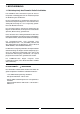
1.2 Beschreibung des Diematic-Delta Schaltfeldes A,B,C PROG 0 2 6 4 8 10 12 14 16 18 20 22 24 A STANDARD 9 AUTO 6,3 AT 4 5 7 TEST STB 6 A B C E D ● Schaltfeld : A. Sicherung 6,3 AT B. Sicherheitstemperaturbegrenzer (110°C) mit manuellem Wiedereinschalten G H 8199N021A-D D. Schalter mit 2 Stellungen "AUTO - Hand Automatik oder Manueller Betrieb ": E. Druckschalter "AUTO - TEST-STB" Prüftaste zur Prüfung des Sicherheitstemperaturbegrenzers C.
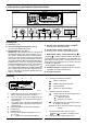
● Dialog-Schaltmodul 5 A,B,C 2 1 PROG 0 2 4 6 8 12 10 14 16 18 20 22 24 6 3 A STANDARD 9 4 7 8 8199N106-D 1. Display (siehe gegenüber) A,B,C : Wahltaste Kreis A, B oder C 2. Temperatureinstellungstasten PROG Wahltaste für Heizprogramm P1, P2, P3 oder P4 Der Regler enthält 4 Programme P1, P2, P3 und P4 die werkseitig eingestellt sind - siehe Beschreibung in ANHANG 2. Das Programm P4 kann nach den eigenen Bedürfnissen programmiert werden (siehe Kapitel 5.3).
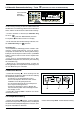
2. WAHL DES ALLGEMEINEN BETRIEBS (AUTOMATIK - MANUELLE SOMMERABSCHALTUNG - MANUELLER BETRIEB ODER PUMPENABSCHALTUNG) 2.1 Automatik-Betrieb Schalter D und F auf AUTO bringen. Diese Stellung erlaubt den automatischen Betrieb mit der Diematic-Delta Regelung. In dieser Stellung können die nachfolgend beschriebenen Betriebsarten mittels der blauen Tasten 4 , , , A,B,C PROG 0 2 4 6 8 10 12 14 16 jederzeit gewählt werden.
Frostschutz-Betrieb : Heizung und Warmwassererwärmung sind außer Betrieb, die Installation wird jedoch überwacht und gegen Frost geschützt. Der Frostschutz-Sollwert für die Raumtemperatur ist auf +6°C voreingestellt. ● Sofortiger Frostschutz für N Tage : Anmerkungen : - Der Frostschutz ist für die Warmwassererwärmung sowie für jeden Kreis, unabhängig von der Einstellung des entsprechenden Raumfühlers, gesichert. Der Frostschutz-Sollwert für die Raumtemperatur ist auf +6°C voreingestellt.
2.2 Manuelle Sommerabschaltung - Taste Taste manuelle Sommerabschaltung A,B,C (befindet sich unter der Abdeckblende) PROG 0 2 4 6 8 10 12 14 16 18 20 22 24 A STANDARD 8199N197(D) Um die Heizung vorzeitig im Sommer abzuschalten und die Warmwassererwärmung jedoch weiter in Betrieb zu halten, wählen Sie die manuelle ”Sommerabschaltung”. - Um diese Funktion zu aktivieren, 5 Sekunden lang auf Taste Die Symbole (unter der Abdeckblende) drücken.
3.
4. WAHL EINES HEIZPROGRAMMES ● Heizungsprogramm Programm-Beschreibung Die DIEMATIC-Delta Regelung enthält 4 werkseitig voreingestellte Programme P1, P2, P3 und P4. Das Heizprogramm P4 kann den eigenen Bedürfnissen angepaßt werden (Urlaub, Schichtarbeit, …).
5.
5.3 Programmierung (Eigenes Heizungs-, Warmwassererwärmungs- und Hilfsausgangs- Programm) Programm P4 (Zeitabschnitte bei Tagbetrieb) : Mo. bis Fr. : Sa. : So. : Warmwassererwärmungs-Programm : 5Uhr - 22Uhr : Freigabe der Warmwassererwärmung 6 bis 8Uhr, 11 bis 13h30, 16 bis 22Uhr 6 bis 23Uhr 7 bis 23Uhr Hilfsausgangsprogramm : 6Uhr - 22Uhr : Freigabe des angeschlossenen Gerätes Diese Programme können den eigenen Bedürfnissen angepaßt werden. Dazu : Kundenspezifische Programme ● EINST.
5.4 Einstellungen Zugang zu Einstellungen und Messungen (5) A,B,C PROG 0 2 4 6 8 10 12 14 16 18 20 22 24 Einstellungen (3) A STANDARD 8199N154(D) (Zeile) anzuzeigen (Siehe Liste der Absätze und Zeilen in ANHANG 1), - Taste drücken, um Absatz "# EINSTELLUNGEN" zu wählen, - auf - Nachfolgende Zeilen können durch Tasten drücken um den entsprechenden Parameter und eingestellt werden : ● BIP : um das Lautsignal zu annulieren oder zu aktivieren (werkseitig : EIN).
6. MELDUNGEN - ALARMMELDUNGEN Bei Betriebsstörungen können folgende Meldungen mit Lautsignal (2 Pieptöne pro Minute, 10 Minuten lang), MELDUNG das man durch Druck auf irgendeine Taste abschalten kann, in der Anzeige erscheinen. WAHRSCHEINLICHE STÖRUNGSURSACHE AUFHAENGEN (diese Meldung erscheint nur auf einem DialogSchaltmodul der von seinem Wandhalter herabgesteckt wurde) SIEHE FERNBED.
Anmerkungen : - KESS. F. DEFEKT und AUSS. F. DEFEKT : Die ganze Anlage geht auf ”Manuell-Betrieb” über : der Kessel ist in Betrieb und wird über den Kesselthermostaten G gesteuert. Alle Pumpen drehen und die Mischer werden nicht mehr mit Strom versorgt. Diese können wenn nötig manuell betrieben werden. Die Temperatureinstellung erfolgt durch den Kesselthermostaten G. - VORL. F. B DEF und VORL. F.
8. WARTUNG 8.1 Eventuelle Änderung der Brennertür-Öffnungsrichtung wenn die ursprungliche Öffnungsrichtung bei der Wartung hindert (z.B. Platzmangel) Werkseitig ist die Brennertür-Öffnung nach rechts vorgesehen. Die Änderung der Öffnungsrichtung nach links erfolgt folgendermaßen : - die mittels 2 Schrauben A (HM 8x12) befestigte Gußachse von der Brennertür abmontieren und obere und untere Scharniere abnehmen indem man die 2 Bundmuttern B (HM 8) aufschraubt.
8.2 Kessel Es wird davon abgeraten, den Kessel zu entleeren, ausgenomen wenn eine unbedingte Notwendigkeit dazu besteht. Regelmäßig den Wasserstand überprüfen und wenn notwendig ergänzen. Keine große Kaltwassermengen in den erhitzten Kessel schlagartig eingeben. Der Kessel muß mindestens vor jeder Heizperiode gereinigt werden, je nach den örtlichen Bestimmungen. Die folgenden Wartungsarbeiten sollen nur bei ausgeschaltetem Kessel und abgeschalteter Stromzufuhr erfolgen.
● Konvektionsbeschleuniger gegebenenfalls entfernen, ● die oberen und unteren Abgaskanäle sorgfältig mit der mitgelieferten Bürste reinigen, ● Feuerraum bürsten, ● den Ruß aus Abgaskanälen und Feuerraum mit Staubsauger, dessen Rohr weniger als 40 mm Durchmesser beträgt, aussaugen. ● Konvektionsbeschleuniger wieder einsetzen, ● Tür wieder schließen und Vorderwand einhängen. Anmerkung : zur Wartung des Brenners siehe Angaben in der Anleitung, die dem Brenner beiliegt. 8199N041B 8.
8199-4233F GTU 110/1100 GTU 110/1100 DIEMATIC Ersatzteile Anmerkung : bei Bestellung der Ersatzteile, ist es unbedingt nötig die Artikel-Nummer des gewünschten Ersatzteils anzugeben. KESSELKÖRPER 5 4 30 3 28 10x 5x 27 26 8 7 5x 5x 6 5x 5x 5x 25 11 10 29 A 13 2 1 9 16 15 14 32 33 20 Alle Modelle außer GTU 116 RN nach 03/98 22 24 12 17 19 23 21 12.
GTU 110/1100 GTU 110/1100 DIEMATIC ISOLIERUNG + KESSELVERKLEIDUNG 46 39 47 36 40 41 49 42 45 40 Visserie / Schrauben / Screws 50 44 8199N107E 2/6
GTU 110/1100 GTU 110/1100 DIEMATIC STANDARD SCHALTFELD 60 59 62 69 70 64 72 74 65 71 63 66 73 68 Accessoires tableau / Zubehör Schaltfeld / Access.
GTU 110/1100 GTU 110/1100 DIEMATIC DIEMATIC-DELTA SCHALTFELD 98 101 99 79 121 83 81 100 103 104 121 82 102 105 88 80 92 106 93 95 97 107 87 94 Accessoires tableau / Zubehör Schaltfeld / Access.
GTU 110/1100 GTU 110/1100 DIEMATIC Ref. Artikel Nr. BEZEICHNUNG Ref. Artikel Nr.
GTU 110/1100 GTU 110/1100 DIEMATIC Rep. Code n° 65 8500-0034 66 DESIGNATION Rep. Code n° DESIGNATION Testschalter 103 8199-4926 Stecker 3-polig (T.S.
10. GARANTIE Mangelrügen und Gewährleistung Für die Haltbarkeit der von uns hergestellten Gußheizkörper und Warmwassererwärmer übernehmen wir die Gewähr für die Dauer von 5 Jahren vom Tage der Inbetriebnahme an gerechnet. Voraussetzung ist sachgemäße Aufstellung, vorschriftsmäßige Bedienung, die Verwendung geeigneter Brennstoffe und die Einhaltung der geltenden Regeln der Technik bei Planung und Ausführung der Anlage.
ANHANG 1 - TABELLE DER BETREIBER-EINSTELLUNGEN - Siehe Erläuterungen in Kapitel 5 - Seiten 9 bis 11. - Die Zeilen sind in der Erscheinungsreihenfolge angegeben. DRÜCKEN dann dann ANZEIGE dann WERKSEINSTEL. # MESSUNGEN TEMP KESSEL TEMP VORLAUF B* TEMP VORLAUF C* TEMP WWE* TEMP RAUM. A* TEMP.SCHWIMMBAD TEMP RAUM. B* TEMP RAUM. C* TEMP AUSSEN TEMP ABGAS* BR. STARTS BR.
ANHANG 1 - TABELLE DER BETREIBER-EINSTELLUNGEN (Fortsetzung) - Siehe Erläuterungen in Kapitel 5 - Seiten 9 bis 11. - Die Zeilen sind in der Erscheinungsreihenfolge angegeben. DRÜCKEN dann ANZEIGE Anmerkung : am Ende des Eingriffes werden die Einstellungen nach 2 Minuten oder nach drücken der Taste gespeichert. EINGESTELLTE PARAMETER WERKS- EINSTELL- EINSTEL.
ANHANG 2 : PROGRAMM-TABELLEN ● HEIZUNGSPROGRAMME : P4 (Werkseinstellung) gewählt für Kreis : … TAG Tagbetrieb P1 : gewählt für Kreis : ……………………… TAG Tagbetrieb Mo. bis So. 6.00 bis 22.00 Mo. bis Fr. Sa. So. P2 : gewählt für Kreis : ……………………… TAG Tagbetrieb Mo. bis So. 4.00 bis 21.00 6.00 bis 8.00, 11.00 bis 13.30, 16.00 bis 22.00 6.00 bis 23.00 7.00 bis 23.00 WWE-Programm (Werkseinstellung) : TAG Freie Warmwassererwärmung : 6.00 bis 22.00 Mo. bis So.
NORD Verkaufsbüro Rheiner Straße 151 48282 Emsdetten Telefon 0 25 72 - 23-400 Telefax 0 25 72 - 23-401 101 OST Oldenburg 102 103 Hamburg MITTE Schwerin 104 108 107 Verkaufsbüro Rheiner Straße 151 48282 Emsdetten Telefon 0 25 72 - 23-450 Telefax 0 25 72 - 23-451 Verkaufsbüro Landsberger Str.