INSTALLATION and SERVICE INSTRUCTIONS USE and CARE INSTRUCTIONS A 1346 G DUAL FUEL COOKER distributed by DèLonghi Pty Ltd
Dear Customer, Thank you for having purchased and given your preference to our product. The safety precautions and recommendations reported below are for your own safety and that of others. They will also provide a means by which to make full use of the features offered by your appliance. Please keep this booklet in a safe place. It may be useful in future, either to yourself or to others in the event that doubts should arise relating to its operation.
FIRST TIME USE THE OVEN It is advised to follow these instructions: Fit the wire racks as described at chapter “Use and care”. Insert shelves and tray. ■ Switch on the empty oven on max to eliminate grease tracks from the heating elements. ■ Clean the interior of the oven with cloth soaked in water and detergent (neutral) then dry carefully.
IMPORTANT PRECAUTIONS AND RECOMMENDATIONS After having unpacked the appliance, check to ensure that it is not damaged. In case of doubt, do not use it and consult your supplier or a professionally qualified technician. Packing elements (i.e. plastic bags, polystyrene foam, nails, packing straps, etc.) should not be left around within easy reach of children, as these may cause serious injuries. ■ Do not attempt to modify the technical characteristics of the appliance as this may become dangerous to use.
1 INSTALLATION CAUTION: ■ ■ ■ ■ ■ ■ This appliance must be installed in accordance with these installation instructions. This appliance shall only be serviced by authorized personnel. This appliance is to be installed only by an authorised person. Incorrect installation, for which the manufacturer accepts no responsibility, may cause personal injury of damage. Always disconnect the cooker from mains power supply before carrying out any maintenance operations or repairs.
CONNECTING THE FEEDER CABLE FEEDER CABLE SECTION type “H05RR-F” To connect the feeder cable to the cooker it is necessary to: 230-240 V 3 x 6 mm2 (**) 230 -240 V3 4 x 4 mm2 (**) Remove the 6 screws that hold shield A behind the cooker. 400 -415 V 3N 5 x 2,5 mm2 (**) ■ Open completely the cable clamp D. 400 -415 V 2N 4 x 4 mm2 (**) ■ Position the U bolts onto terminal block B (fig. 1.1 - 1.2). ■ ■ Insert the feeder cable into the cable save P.
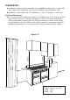
CLEARANCES ■ ■ Installation clearances and protection of combustible surfaces shall comply with the current local regulations eg. AG 601 (AS 5601) Gas Installations code. Installation shall comply with the dimension in Fig 1.3 bearing in mind that Overhead Clearances ■ In no case shall the clearances between the highest part of the cooker be less than 600mm or for an overhead exhaust fan 750mm.
Rear and Side Clearances ■ Where the dimensions from the periphery of the nearest burner to any vertical combustible surface is less than 200mm the surface shall be protected in accordance with the standards to a height of not less than 150mm above the cooking surface for the full width or depth of the cooking surface ■ Where the dimensions from the periphery of the nearest burner to any horizontal combustible surface is less than 200mm, the horizontal surface shall be greater than 10mm below the surface of
MOVING THE COOKER WARNING To move the cooker always ensure two people carry out this manoeuvre to prevent damage to the appliance (fig. 1.5). Figure 1.5 WARNING Be carefull: do not lift the cooker by the door handle (fig. 1.6). WARNING When moving cooker to its final position DO NOT DRAG (fig. 1.7). Lift feet clear of floor (fig. 1.5). Figure 1.6 Figure 1.
BACKGUARD Before installing the cooker, assemble the backguard “C” (fig. 1.8). ■ The backguard “C” can be found packed at the rear of the cooker. ■ Before assembling remove any protective film/adhesive tape. ■ Assemble the backguard as shown in figure 1.8 and fix it by screwing the 5 screws “A”. Figure 1.
ANTI-TILT BRACKET ■ WARNING: In order to prevent accidental tiè p ping of the appliance, for example by a child climbing onto the open oven door, the stabilizing means must be installed. Please refer to instructions for installation. 1. The anti-tilt bracket has to be attached as shown on figure below, it has to be fixed on the floor and on the rear wall by no. 4 (four) suitable screws (not supplied). 2. After fixing the anti-tilt bracket, slide cooker into place.
GAS SUPPLY: ■ The connection must be performed by an authorised person according to the relevant standards. ■ Before connecting the appliance to the gas main, mount the brass conical adaptor onto the gas inlet pipe, upon which the gasket has been placed (figures 1.10a1.10b). Conical adaptor and gasket are supplied with the appliance (packed with conversion kit for use with Natural gas or Propane gas). ■ This appliance is suitable for use with Natural Gas or Propane gas.
1. After connecting the gas supply, check the piping and connections for leaks using a soap and water solution. The presence of bubbles indicates a leak, tighten or replace connections as appropriate. Warning: Do not use any naked flame to check for leaks. Figure 1.11 2. Adjust the test point pressure or supply pressure to the value which is appropriate for the gas type. 3. The operation of the appliance must be tested when installation is completed. 4.
CONVERSION PROCEDURE (to convert to LPG Propane) REPLACING THE INJECTORS This appliance is suitable for use with Natural gas or Propane gas (check the “gas type” sticker attached to the appliance). A label stating the type of gas used after replacing the injectors must be attached at the rear of the appliance, in proximity of the gas inlet connection. The nominal gas consumption and injector size details are provided in table at page 16.
MINIMUM BURNER SETTING ADJUSTMENT Check whether the flame spreads to all burner ports when the burner is lit with the gas tap set to the minimum position. If some ports do not light, increase the minimum gas rate setting. Check whether the burner remains lit even when the gas tap is turned quickly from the maximum to the minimum position. If the burner does not remain lit, increase the minimum gas rate setting. The procedure for adjusting the minimum gas rate setting is described below.
TABLE FOR THE CHOICE OF THE INJECTORS Natural gas 1.0 Test Point Pressure [kPa] BURNER Propane gas 2.75 Injector Orifice Dia. Gas Consumption Injector Orifice Dia. Gas Consumption [mm] [MJ/h] [mm] [MJ/h] Auxiliary (A) 0.85 3.60 0.53 3.60 Semi-rapid (SR) 1.12 6.30 0.70 6.30 Rapid (R) 1.45 10.30 0.91 10.80 Triple ring (TC) 1.65 13.30 0.95 11.90 LUBRICATION OF THE GAS TAPS If the gas tap becomes stiff, it is necessary to dismantle it carefully and clean it with petroleum spirit.
12 USE and CARE CAUTION: ■ This appliance must be used only for the task it has explicitly been designed for, that is for domestic cooking of foodstuffs. Any other form of usage is to be considered as inappropriate and therefore dangerous. ■ Do NOT place combustible materials or products on this appliance at any time. ■ Do NOT spray aerosols in the vicinity of this appliance while it is in use.
USING THE TOP RIGHT AND THE BOTTOM LEFT OVEN FOR THE FIRST TIME (fig. 2.2) Slide off the sliding shelves to the oven wall by unscrewing the 2 screws as in Fig. 2.4. The grill is secured to the rear wall of the oven on a hinge system that allows it to be lowered to allow proper access when cleaning the oven ceiling (fig. 2.3). ■ Clean the inside of the oven with a cloth soaked in water and neutral detergent and dry thoroughly. ■ Figure 2.2 Figure 2.
Assemble the sliding shelves on the oven wall as in Fig. 2.4.The sliding shelves facilitate the insertion and removal of shelves during cooking; they stop when pulled out to the maximum position. These shelves support all accessory trays and are dishwasher safe. ■ Slide in the grease filter on the back of the oven as in Fig. 2.1. ■ ■ Position the shelf and tray as per Fig. 2.5. ■ Switch on the bottom left oven as described at page 35. ■ Switch on the top right oven as described at pages 39. Figure 2.
USING THE TOP LEFT OVEN FOR THE FIRST TIME (fig. 2.6) Clean the inside of the oven with a cloth soaked in water and neutral detergent and dry thoroughly. ■ Assemble the sliding shelves on the oven wall as in Fig. 2.7.The sliding shelves facilitate the insertion and removal of shelves during cooking; they stop when pulled out to the maximum position. These shelves support all accessory trays and are dishwasher safe. ■ Position the shelf and tray as per Fig. 2.8.
TILTING GRILL OF THE TOP LEFT OVEN ■ ■ (fig. 2.11) The grill is secured to the rear wall of the oven on a hinge system that allows it to be lowered to allow proper access when cleaning the oven ceiling (fig. 2.11). In the front the grill is secured to the ceiling by a hook A. Unlocking the tilting grill (fig. 2.9) Locking the tilting grill (fig. 2.10) 1. Open the hook A. 2. Gently pull down the grill as shown in the figure 2.11. 1. Gently lift up the grill. 2. Close the hook A on the grill bar.
CONTROL PANEL Figure 2.12 20 21 19 18 17 16 A U T O 1 2 3 4 5 6 7 8 9 10 11 12 13 14 15 CONTROL PANEL - Controls description 1. Conventional oven thermostat knob (top left oven) 2. Conventional oven switch knob (top left oven) 3. Fan oven thermostat knob (bottom left oven) 4. Fan oven switch knob (bottom left oven) 5. Front left triple-ring burner control knob (4) 6. Rear left semi-rapid burner control knob (2) 7. Central rear left rapid burner control knob (3) 8.
13 COOKING HOB Figure 3.1 2 4 GAS BURNERS 1. 2. 3. 4. Auxiliary burner (A) Semi-rapid burner (SR) Rapid (R) Triple ring burner (TC) 3 6 1 5 2 4 Natural Gas MJ/h Propane gas MJ/h 3.6 6.3 10.3 13.3 3.6 6.3 10.8 11.9 GLASS CERAMIC ZONES 5. 3 circuits hotplate Ø 145 mm - 1200 W 6. 3 circuits hotplate Ø 180 mm - 1700 W Note: The electric ignition is incorporated in the knobs.
LIGHTING GAS BURNERS FITTED WITH SAFETY VALVE DEVICE AND ELECTRONIC IGNITION Figure 3.2 ■ Check that the electricity is switched on to allow spark ignition. ■ Make sure that all controls are turned to zero. ■ The gas flow to the burner is controlled by taps with safety cutout device. If the burner flame should go out, the safety cut-off valve will automatically stop the gas flow. The switch for the electric ignition is incorporated in the knobs.
CHOICE OF BURNER The burner must be chosen according to the diameter of the pans and energy required. For optimum efficiency use a wok or pan no smaller than 230mm diameter. Figure 3.3 do not use pans with concave or convex bases Burners Pan diameter Auxiliary Semi-rapid Rapid Triple ring Wok 12 - 14 cm 16 - 24 cm 24 - 26 cm 26 - 28 cm max 36 cm Saucepans with handles which are excessively heavy, in relationship to the weight of the pan, are safer as they are less likely to tip.
GRATE FOR SMALL PANS ■ Figure 3.4 This grate (fig. 3.4) is to be placed on top of the (smaller) auxiliary burner when using small diameter pans, in order to prevent them from tipping over. CORRECT USE OF TRIPLE-RING BURNER ■ The flat-bottomed pans are to be placed directly onto the pan-support. ■ To use the WOK, you must place the wok stand in the CORRECT position as shown in Fig. 3.5 - 3.6. IMPORTANT: The special grille for wok pans (fig. 3.
VITROCRAMIC HOB The ceramic surface of the hob allows a fast transmission of heat in the vertical direction, from the heating elements underneath the ceramic glass to the pans set on it. The heat does not spread in the horizontal direction, so that the glass stays “cool” at only a few centimetres from the cooking plate. The 2 cooking zones are shown by disks on the ceramic surface.
COOKING HINTS Figure 3.9 Switch position 1 Switch position TYPE OF COOKING 0 Switched OFF 1 2 For melting operations (butter, chocolate). 2 To maintain food hot and to heat small quantities of liquid (sauces, eggs). 3 To heat bigger quantities; to whip creams and sauces. (vegetables, fruits, soups). 3 4 Slow boiling, i.e.: meats, spaghetti, continuations of cooking of roasts, potatoes. 4 For every kind of frying, cutlets, uncovered cooking, i.e.: risotto.
RESIDUAL HEAT INDICATOR The appliance also features 2 warning lights (located in the control panel above the control knobs) which are connected to the corresponding plate. When the temperature of a cooking plate is above 60°C, the relevant warning lights will also light up to warn of heat on the surface of the hob. This light also stays on after the cooking plate has been switched off to show that the hob surface is still hot.
COOKING HINTS: ■ To reduce the cooking time, you can turn the control knob to the max when you switch the plate on. After a short time you can set the control knob to the position required for cooking. ■ You should only use pots and pans with flat bases (pans with the test mark for glass-ceramic hobs are available from specialist shops). The diameter of the pan should match that of the cooking plate (or be slightly bigger) to make the most of the energy.
CLEANING Before you begin cleaning make sure that the appliance is switched off. ■ Remove spillages and other types of incrustations. ■ Dust or food particles can be removed with a damp cloth. ■ If you use a detergent, please make sure that it is not abrasive or scouring. Abrasive or scouring powders can damage the glass surface of the hob. ■ All traces of the cleaner must be removed with a damp cloth. ■ Do not put articles on the hob which can melt: i.
41 CONVECTION OVEN (Top left oven) NOTE: Upon first use, it is advisable to operate the oven at the maximum temperature (thermostat knob on position MAX) for 60 minutes in the position and for another 15 minutes in the mode in order to eliminate any traces of grease from the electrical resistances. WARNING: The door is hot use the handle.
TEMPERATURE KNOB (Fig. 4.1) This only sets the cooking temperature and does not switch the oven on. Rotate clockwise until the required temperature is reached (from 50°C to MAX). FUNCTION SELECTOR KNOB (Fig. 4.2) Rotate the knob clockwise to set the oven for one of the following functions: OVEN LIGHT The oven is equipped with a light that illuminates the oven to enable visually controlling the food that is cooking. This light is controlled by the selector knob (fig. 6.
UPPER HEATING ELEMENT In this position only the upper element is switched on. Heat is distributed by natural convection. The thermostat can be set between 50 and 150°C; higher temperatures are not available. Recommended for: This mode is particularly suitable to complete cooking of dishes that require higher temperature at the top. GRILLING The infra-red heating element is switched on. The heat is diffused by radiation. Use with the oven door closed and the thermostat knob to between 50°C and 225°C.
51 FAN OVEN (Bottom left oven) GENERAL FEATURES With your new Fan oven it is possible to cook a variety of food using the 2 different cooking functions. The 2 positions, thermostatically controlled, are obtained by 2 heating elements. – Grill element 2000 W – Circular element 2200 W Figure 5.
Figure 5.3 75 50 Figure 5.2 200 5 12 225 100 250 175 150 TEMPERATURE KNOB (Fig. 5.2) This only sets the cooking temperature and does not switch the oven on. Rotate clockwise until the required temperature is reached (from 50 to 250°C). FUNCTION SELECTOR KNOB (Fig. 5.3) Rotate the knob clockwise to set the oven for one of the following functions: OVEN LIGHT By setting the knob to this position the oven light will come on. (15 W). The oven remains alight while any of the functions is on.
HOT AIR COOKING The circular element and the fan are on. The heat is diffused by forced convection and the temperature must be regulated between 50° and 250 °C with the thermostat knob. It is not necessary to preheat the oven. Recommended for: For foods that must be well done on the outside and tender or rare on the inside, i. e. lasagna, lamb, roast beef, whole fish, etc. GRILLING The infra-red heating element is switched on. The heat is diffused by radiation.
REGENERATION Set the switch to position and the thermostat knob to position 150° C. Bread becomes fragrant again if wet with a few drops of water and put into the oven for about 10 minutes at the highest temperature. ROASTING To obtain classical roasting, it is necessary to remember: – that it is advisable to maintain a temperature between 180 and 200 °C. – that the cooking time depends on the quantity and the type of foods.
16 MULTIFUNCTION OVEN (Top right oven) WARNING: The door is hot, use the handle. OPERATING PRINCIPLES Heating and cooking in the MULTIFUNCTION oven are obtained in the following ways: a. by normal convection The heat is produced by the upper and lower heating elements. GENERAL FEATURES As its name indicates, this is an oven that presents particular features from an operational point of view. In fact, it is possible to insert 7 different programs to satisfy every cooking need.
Figure 6.2 75 50 Figure 6.1 100 250 200 1 25 225 175 150 THERMOSTAT (Fig. 6.1) This only sets the cooking temperature and does not switch the oven on. Rotate clockwise until the required temperature is reached (from 50 to 250°C). The elements will turn ON or OFF automatically according to the energy need which is determined by the thermostat. FUNCTION SELECTOR KNOB (Fig. 6.
GRILLING The infra-red heating element is switched on. The heat is diffused by radiation. Use with the oven door closed and the thermostat knob to between 50° and 225°C. Note: It is recommended that you do not grill for longer than 30 minutes at any one time. Attention: the oven door becomes very hot during operation. Keep children away. For correct use see “USE OF THE GRILL” Recommended for: Intense grilling action for cooking with a broiler; browning, crisping, “au gratin”, toasting, etc.
VENTILATED GRILL COOKING The infra-red ray grill and the fan are on. The heat is mainly diffused by radiation and the fan then distributes it throughout the oven. The temperature must be regulated between 50° and 200°C maximum with the thermostat knob. It is necessary to preheat the oven for about 5 minutes. Use with the oven door closed. Note: It is recommended that you do not grill for longer than 30 minutes at any one time. Attention: the oven door becomes very hot during operation. Keep children away.
COOKING ADVICE STERILIZATION Sterilization of foods to be preserved, in full and hermetically sealed jars, is done in the following way: a. Set the switch to position . b. Set the thermostat knob to position 185 °C and preheat the oven. c. Fill the dripping pan with hot water. d. Set the jars onto the dripping pan making sure they do not touch each other and the door and set the thermostat knob to position 135 °C.
GRILLING AND “AU GRATIN” As the hot air completely covers the food to be cooked, grilling may be done with the food on rack in the oven. The knob should be switched to position . Set the thermostat knob between 50°C and 200°C maximum and after having preheated the oven, simply place the food on the grid. Close the door and let the oven operate until grilling is done. Adding a few dabs of butter before the end of the cooking time gives the golden “au gratin” effect. Grilling with the oven door closed.
ELECTRONIC PROGRAMMER (Right main oven only) The electronic programmer is a device which groups together the following functions: ■ 24 hours clock with illuminated display ■ Timer (up to 23 hours and 59 minutes) ■ Program for automatic oven cooking (right oven only) ■ Program for semi-automatic oven cooking (right oven only) Description of the buttons: Timer Cooking time End of cooking time Manual position and cancellation of the inserted cooking program Plus function to increase the number shown on the di
ELECTRONIC CLOCK (fig. 6.4) The illuminated figures on the clock represent hours and minutes on 24 hour clock. When first connected, or after a power failure, three zeros will flash on the display. To set the time press the button and then the or Please note that changing the hour button deletes any cooking program.
ELECTRONIC TIMER The timer program consists only of a buzzer which may be set for a maximum period of 23 hours and 59 minutes. If AUTO is flashing on the panel, push the button. To set the time, push the button and the or until you obtain the desired time in the panel (fig. 6.6). Having finished the setting, the clock hour will appear on the panel and the symbol will be lighted. The countdown will start immediately and may be seen at any moment on the panel by simply pressing the button .
AUTOMATIC OVEN COOKING To cook food automatically in the oven, it is necessary to: 1.Set the length of the cooking time 2.Set the end of the cooking time 3.Set the temperature and the oven cooking program. These operations are performed as follows: 1.Set the length of the cooking time by pushing the button and the button to advance, or to go back if you have passed the desired time (fig. 6.7). The AUTO and the symbol will be on. 2.
SEMI - AUTOMATIC COOKING This function is only used to set the END of the cooking time of the oven. There are two ways of setting this function. 1. Set the length of the cooking time by pushing the button and the button to advance, or to go backwards (Fig. 6.7). This sets the desired “stop” time. or 2.Set the end of the cooking time by pushing the button and the button to advance, or to go backwards if you have passed the desired time (Fig. 6.8). AUTO and the symbol will be on.
71 Cooking chart RECOMMENDED COOKING TEMPERATURE Food °C °F Gas Mark Shelf Position* Cooking Time (approx) CAKES Victoria sandwich Small cakes/buns Maidera cake Fruit cake Rich fruit cake Scones 190 190 180 170 150 225 375 375 350 325 300 425 5 5 4 3 2 8-9 2 or 3 1 and 2 2 or 3 3 3 or 4 2 20-25 mins 15-20 mins 20 mins 13/4 hours 21/2 hours 8-10 mins PASTRY Puff Short crust Plate tarts Quiches and flans 225 200 200-210 200-210 425 400 400-410 400-410 8-9 6 6 6 2 2 1 or 2 1 or 2 10-20 mins
18 Maintenance Period Daily Monthly 3 - 4 Yearly Cleaning and Maintenance Description • Clean gas cooktop as per instructions below • Remove burner caps, burner rings & base and clean using non abrasive detergent & rinse in cold water & dry thoroughly before replacing back on hob • Clean ignitor tip & thermocouple using damp soapy cloth and dry thoroughly • Contact your local authorized gas Service Agent to perform a thorough check on all gas components on the gas cooker GENERAL ADVICE ■ ■ ■ ■ ■ Before
STAINLESS STEEL SURFACES (UNCOATED) ■ ■ The hob + sides are made from un-coated stainless steel. Can be cleaned with an appropriate stainless steel cleaner. CLEANING THE VITROCERAMIC HOB ■ See page 31. OVEN ■ ■ ■ The oven with smooth enamel must be cleaned after every use, using suitable products. Please note that after using the oven for 30 minutes on the highest temperature eliminates most grime reducing it to ashes.
Figure 8.1 BURNERS They can be removed and washed only with soapy water. Detergents can be used but must not be abrasive or corrosive. C ■ Do not use abrasive sponges or pads. ■ Do not put in dishwasher. ■ After each cleaning, make sure that the burner-caps, as well as the burners, have been well wiped off and CORRECTLY POSITIONED. ■ It is essential to check that the burner flame distributor F and the cap C has been correctly positioned (fig. 8.1) - failure to do F so can cause serious problems.
CLEANING THE INSIDE OF THE OVENS ■ The ovens must be cleaned after every use. Please note that after using the oven for 30 minutes on the highest temperature eliminates most grime reducing it to ashes. ■ To cleaning remove the sliding shelves as described on the following pages: – pages 18-19 for bottom left oven and top right oven – page 20 for top left oven With the oven warm, wipe the inside walls with a cloth soaked in very hot soapy water or another suitable product.
REMOVING THE BOTTOM LEFT OVEN DOOR The oven door can easily be removed as follows: ■ ■ ■ ■ ■ ■ Open the door. Unscrew the 4 screws of the bottom hinge (fig. 8.7) Hold the door and unscrew the 3 screws of the upper hinge (fig. 8.6). Remove the door following the arrow C (fig. 8.6 - 8.7) Rest the door on a soft surface. To replace the door, repeat the above steps in reverse order. Figure 8.6 DRAWER ■ The drawer (fig. 8.5) comes out like a normal drawer.
REMOVING THE OVEN DOORS (top left and right ovens) Figure 8.8a The oven doors can easily be removed as follows: ■ Open the door to the full extent (fig. 8.8a). ■ Open the lever “A” completely on the left and right hinges (fig. 8.8b). Figure 8.8b ■ Hold the door as shown in fig. 8.8. ■ Gently close the door (fig. 8.8) until left and right hinge levers “A” are hooked to part “B” of the door (fig. 8.8b) ■ Withdraw the hinge hooks from their location following arrow “C” (fig. 8.8d).
Service and Maintenance If the ignition spark fails to ignite or does not light the gas, check the following items before calling our Customer Service Centre to obtain the nearest Authorised Service Agent: ■ ■ ■ Burner is reassembled and located correctly. Spark electrode and white ceramic are clean and dry. 240 VAC power supply is connected. Contact the local gas utility or our Customer Service Centre to obtain the nearest Authorized Service Agent. ■ ■ ■ You can smell gas when all burners are turned on.
TM1 LF1 S1 P2 P1 P3 CF S G C 3 4 1 2 5 F1 PA TL1 * TM2 A TL2 S2 V 1a 2a 3a 4a 5a 1 CIR G1 LF2 2 1 2 3 4 5 F2 3 4 5 4 3 1 P2 P1 P3 T 2 M S3 CN P1 3 4 1 2 5 F4 S4 S5 4 3 1 P2 P1 P3 2 P2 CN 3 4 1 2 5 F5 M L N 1 1a T TL3 L/8 N/7 PR TM3 8 9 10 11 9a 10a 11a LF3 CIR1 G2 C1 CF1 S1 V1 6 7 8a 7a 5a 6a 2 4 5 4a 1 3 2a 3a 1a F3 S6 WIRING DIAGRAM
1 2 80° ) 40° ) 3 4 160° ) 120° ) 5 200° ) 6 240° ) 7 280° ) 8 320° ) Convection cooking with ventilation FUNCTION Maintaining temperature after cooking or slowly heating foods FUNCTION Ventilated grill cooking FUNCTION Hot air cooking FUNCTION Defrosting frozen foods FUNCTION Grilling FUNCTION Traditional convection cooking FUNCTION Oven light FUNCTION 6 7 8 9 10 11 FUNCTION 6 FUNCTION 5 FUNCTION 4 FUNCTION 3 FUNCTION 2 FUNCTION 1 POSITION 0 P3 5 2 P2 1 3
Rif. 1639.6 Cod.