GENERAL SERVICE MANUAL INDEX DRIVES WARNING This is a controlled document. It is your responsibility to deliver this information to the end user of the CAMCO or FERGUSON product. Failure to deliver this could result in your liability for injury to the user or damage to the machine.
Table of Contents Introduction........................................................................................................................... 2 How to Use This Service Manual.......................................................................................... 2 Warranty ............................................................................................................................... 2 Warnings and Cautions ........................................................................
Introduction CAMCO Index Drives are engineered and manufactured to very high tolerances which necessitate careful inspection and maintenance. This manual is a general guide to lubrication, troubleshooting and general information about index drives. In addition to this General Service Manual, Industrial Motion Control, LLC (IMC) has other service manuals devoted to the specific model CAMCO index drive you are using. The model-specific service manuals cover disassembly and assembly of the major components.
Warnings and Cautions Statements in this manual preceded by the words WARNING or CAUTION and printed in italics are very important. We recommend you take special notice of these during service or repair. WARNING Means there is the possibility of personal injury to yourself or others. CAUTION Means there is the possibility of damage to the CAMCO unit.
After motion is complete the cam is considered to be in dwell for the reminder of the 360° rotation. During dwell the output of the Index Drive is stationary even though the input shaft continues to rotate. Example: For a 270° motion, during 270° of input rotation the output shaft makes one index. During the remaining 90° of input rotation the output is stationary. IMPORTANT NOTE: Some CAMCO units are called "type 2" units. In this case the cam has two motion periods and two dwell periods on the cam.
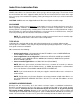
Index Drive Lubrication Data OIL LEVEL CAMCO Index Drives are furnished with a "bulls-eye" type oil level sight gauge. The oil level should be checked when the unit is stopped at which time the oil level should reach the center of the sight glass (see page 3 for estimated oil capacity). During oil changes this "bulls-eye" can be removed for cleaning. CAUTION: CAMCO units are shipped without oil. Be sure to fill prior to initial startup.
Index Drive Oil Capacities (Approximate) For indexers mounted in the normal* position. Consult IMC for units not listed. Model No. US. Metric Model No. U.S. (quarts) (liters) (quarts) Grease filled** 80RDM 40RGD/S 6 oz. 601RDM 2 2 50RGD/S 16 oz. 902RDM 3 3 70RGD/S 20-24 oz. 1100RDM 8 8 80RGD/S 30-38 oz.
4. Check shaft -- remove surface nicks, burrs and grooves and look for spiral machine marks that can damage the seal lip. 5. Check shaft end -- remove burrs or sharp edges. The shaft end should be chamfered. 6. Check splines and keyways -- smooth any sharp edges and when necessary protect the seal lip with an assembly sleeve or shim stock. Round the edges of the spline or keyway as much as possible and lubricate with a hard, fibrous grease. 7.
Gear Reducer Lubrication Data OIL LEVEL Most reducers are furnished with a "bull’s eye" type sight glass or a pipe plug to indicate oil level. In either case an oil level tag is affixed to the reducer near the oil level indicator. Oil level should be checked with the unit stopped. Estimated oil capacities for standard reducers are listed on page 13. CAUTION: IMC ships all gear reducers without oil (except the R180, R225 and R260). Be sure to fill to proper level prior to startup.
Overload Clutch GENERAL The CAMCO plunger-type output overload clutch is a reliable minimum service overload device requiring very little attention (in a semi-clean environment) during its service life. The environment is an important factor in the successful functioning of this device. A dusty or corrosive environment may require special preparation or attention. (Contact IMC for special modifications). High humidity, contaminants, or wash down applications may also require special protection.
3. Long Term Storage (Outdoors) for Periods up to One Year. Proceed as in (2) above with the following additions. (a) After filling the unit with oil, plug the breather hole with a pipe plug and wire the breather to the unit. (b) Coat all exposed shafting with long term rust preventative. 4. Extended Storage periods Exceeding One Year. (a) Coat all exposed shafts with a long term rust preventative. (b) Place the unit in a heavy plastic bag and put approximately 1/2 oz. #260 "VPI" powder in the bag.
5. All followers are worn. Rebuilding by factory is best remedy. 6. Output shaft to follower wheel connection is loose. Factory repair is recommended. 7. Customer output member connection loose. Tighten output member and dowel in place. SYMPTOM: INDEXER IS NOISY 1. Check if output is backlash-free in dwell. 2. Check for excess looseness in motion. Cam or follower could be broken 3. Is the noise from the reducer rather than the indexer? 4. Occasionally, variable speed D.C.
Recommended Input Configuration The prime objective of a good input connection to an Index Drive is to maintain a constant shockfree velocity. Both the type of motor driving the indexer and the type of connection is of equal importance. Here we explain some of the advantages and disadvantages of these factors. 1. Worm gear reducers with a high reduction provide two features. First, the flywheel energy due to the high speed of the input.
Recommended Output Configuration The objective of a good output connection to an Index Drive is to make torque levels predictable and limited in magnitude. A good connection is rigid and free of backlash. IMC recommends that a CAMCO output overload clutch be used with index drives whenever possible. This will prevent costly damage to the unit in the event of a jam and eliminate costly down time. Our preference for output connections is as follows and in this order: 1. Flange mountings are superior.
Cam & Limit Switch Functions Cam & Limit Switches serve two purposes: 1. Some customers desire an electrical signal somewhere during dwell in order to trigger another device such as a cylinder, punch press, loader, etc. 2. To signal the dwell position for a cycle on demand application. In cycling, the input is signaled to stop somewhere in dwell position. This stopping may be done either by stopping the motor or using a clutch brake to disconnect the motor from indexer input.
How to Order Parts Please refer to the Parts List applicable to your specific model as shown in the model-specific service manual. This Parts List is for a standard Index Drive. If you feel your drive in non-standard or you are in doubt you should contact IMC Customer Service (847) 459-5200 and request a bill of material for your specific unit (based on serial number). You may order parts by using the Standard Bill of Material even if your unit is non-standard.
How to Return Equipment for Repair Please contact the IMC Repair Department in Wheeling, Illinois at (847) 459-5200 for a "Return Material Authorization" Number (RMA#). The following information is required of a unit for repair, conversion or warranty. 1. Purchase order number 2. Customer name 3. Customer billing address 4. Customer shipping address 5. Person to contact, upon inspection, with delivery and price. 6. Telephone number 7. Model number (located on name plate) 8.
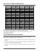
Indexer Weights Right Angle Model 301RA 400RA 401RA 512RA 662RA 663RAD 900RAD 1200RAD Parallel Model 250P 387P 512P 662P 900P 1200P 1800P lbs 15 33 55 80 160 130 220 850 kg 6.8 15.0 24.9 36.3 72.6 59.0 99.8 385.6 lbs 18 55 135 430 750 1100 3000 kg 8.2 24.9 61.2 195.0 340.2 499.0 1360.8 Roller Gear Model 350RG 500RG 600RG 700RG 80RDM 601RDM 902RDM 1100RDM 1305RDM 1800RDM 425RD 800RD 1301RD 1801RD lbs 35 350 390 400 19 70 130 192 305 1400 110 450 1000 2400 kg 15.9 158.8 176.9 181.4 8.6 31.8 59.0 87.
Recommended Tightening Torque Values for Cap Screws SAE Grade 2 Torque Spec. (ft/lbs) Thread Size into Aluminum .250-20 3.7 .250-28 4.1 .312-18 7.3 .375-16 13 .375-24 15 .437-14 21 .437-20 24 .500-13 33 .500-20 36 .562-12 46 .562-18 53 .625-11 66 .625-18 73 .750-10 116 .750-16 133 .875-9 113 .875-14 119 1.00-8 166 1.00-14 186 1.12-7 233 1.12-12 266 1.25-7 333 1.25-12 366 1.50-6 580 1.50-12 563 Spiralock Thread .250-20SL* 4.
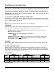
IMPORTANT!!! Cam Follower Installation Procedure The H9 thru H32 (.287” thru 1.00” diameter) Cam Followers require a Steel Ball/Set Screw and an insertion gage for installation. The steel ball/set screw is used to anchor the cam followers to the follower wheel and the insertion gage kit is used to insure proper installation. The new cam followers need to be pressed onto the follower wheel to the position prescribed by the gage (if they are pressed in too far, the will not turn freely).
Table: Cam Follower Anchoring Method MODEL CAM FOLLOWER DIAMETER (INCHES) ANCHORING METHOD MINIATURE RGD/RGS H9 thru H24 .287 thru .750 BALL/SET SCREW 350RGD / RGS H20 thru H32 .750 thru 1.00 BALL/SET SCREW 350RG H20 thru H24 .625 thru .750 SET SCREW ONLY * 500RGD / RGS H28 thru H32 .875 thru 1.000 BALL/SET SCREW 500RG H28 thru H32 .875 thru 1.000 SET SCREW ONLY * 80RDM H16 .500 BALL/SET SCREW 80RDM H20 .625 SET SCREW ONLY * 600RDM H20 thru H24 .625 thru .750 SET SCREW ONLY * 601RDM H20 thru H24 .625 thru .
MODEL CAM FOLLOWER 110RGD / RGS H24 110RGD / RGS H28 140RGD / RGS H24 140RGD / RGS H28 350RGD / RGS H20 350RGD / RGS H24 350RG H20 350RG H24 500RGD / RGS H28 500RG H28 80RDM H16 80RDM H20 600RDM H20 600RDM H24 601RDM H20 601RDM H24 901RDM H20 901RDM H24 901RDM H28 902RDM H20 902RDM H24 902RDM H28 1305RDM H20 1305RDM H24 1305RDM H28 425RD H24 425RD H28 800RD H28 150RPP ROTARY H20 150RPP LIFT H20 150RPP LIFT H24 300RPP LIFT & H24 ROTARY 500RPP ROTARY H24 500RPP ROTARY H28 500RPP LIFT H24 500RPP LIFT H28 900RP
MODEL CAM FOLLOWER DIAMETER (INCH) 80RGD / RGS H18 .563 80RGD / RGS H20 thru H28 .625 thru .875 350RG H20 thru H24 .625 thru .750 350RGD / RGS H20 thru H24 .625 thru .750 350RGD / RGS H32 1.000 500RG H28 .875 500RGD / RGS H28 .875 500RG H32 1.000 500RGD / RGS H32 1.000 80RDM H16 .500 80RDM H20 .625 600RDM H20 thru H24 .625 thru .750 601RDM H20 thru H24 .625 thru .750 900RDM H32 1.000 901RDM H20 thru H28 .625 thru .750 902RDM H20 thru H28 .625 thru .
NOTES 23
NOTES 24
Industrial Motion Control, LLC CAMCO & FERGUSON Products 1444 South Wolf Road Wheeling, IL 60090 USA ph: 847-459-5200 toll-free: 800-645-5200 fax: 847-459-3064 camco@destaco.com www.camcoindex.com ISO 9001:2000 Registered DE-STA-CO Headquarters Auburn Hills, Michigan USA 248-836-6700 marketing@destaco.com DE-STA-CO Europe Germany +49-6171-705-0 europe@destaco.com DE-STA-CO Asia Thailand +66-2-326-0812 info@destaco.com DE-STA-CO South America Brazil 0800-124070 samerica@destaco.com www.destaco.