® The Driving Force in Automation OVERLOAD CLUTCHES FOR INDEX DRIVES “WARNING” “WARNING” This is a controlled document. It is your responsibility to deliver this information to the end user of the CAMCO indexer. Failure to deliver this, could result in your liability for injury to the user or damage to the machine. For copies of this manual call your Customer Service Representative 800/645-5207.
INSTALLATION, OPERATION AND MAINTENANCE INSTRUCTIONS 7. Dowel pins and mounting screws must not protrude from the drive plate or driven member as the clutch could become a solid coupling. SAFETY INSTRUCTIONS 1. Read your Overload Clutch InstallationOperation Instructions thoroughly before operating the unit, for your safety and the protection of your unit. 8. High humidity, contaminants, or wash down applications may cause rust within the clutch, resulting in operational failure.
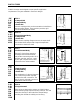
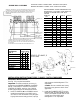
CLUTCH TYPES CAMCO clutches are designed to meet specific application requirements. They are available in five basic designs. .39C 2.3C 6.0C 11C 25C 41C TYPE C .39FC 2.3FC 6.0FC 11FC 25FC 41FC TYPE FC .39F 2.3F 6.0F 11F 25F 41F 140F .39S 2.3S 6.0S 11S 25S 41S 2.8D 4.0D 7.8D 18D 31D 32D 61D 130D • Clamped Hub • Clamped Body • Shrink Disc A clutch coupling which can be mounted on Index Drives without output flanges. They provide a positive, rigid connection between two shafts.
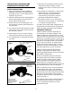
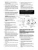
INSTALLATION AND REMOVAL INSTRUCTIONS FOR SHRINK DISCS IMPORTANT! Carefully Clean Shaft & Hub Bore & Keep Free of Any Lubricant Outer Collars Shrink Discs are supplied ready for installation. However, prior to tightening of locking screws it is necessary to remove wooden spacers located between outer collars, which are used during shipment of Shrink Discs.
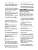
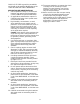
SHRINK DISC COUPLINGS IFOR RIGID SHAFT CONNECTIONS- TRANSMIT TORQUES & BENDING MOMENTS- PERMIT AXIAL & ANGULAR TIMING RECOMMENDED SLEEVE DIMENSIONS FOR SHRINK DISC COUPLINGS USING SERIES 01 & SERIES 03 SHRINK DISC SIZE 140 & LARGER SHRINK DISC (PREFERABLY USE UNITS WITH INTEGRATED HUB STOP) REFER TO SHRINK DISC SPECIFICATION TABLE FOR SELECTION OF SHRINK DISC TO MEET YOUR TORQUE & SHAFT SIZE REQUIREMENTS. CONSULT WITH US IF A BENDING MOMENT HIGHER THAN 25% OF RATED TORQUE HAS TO BE TRANSMITTED.
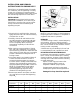
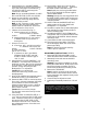
3. Align the PLUNGERS with the tapered seats in the DRIVE PLATE. 5. Place BODY with the PLUNGERS face down on a solid surface. 4. Type C Clutch COUPLING: Insert mounting screws through the FLANGE PLATE into the tapped holes in the BODY π . Alternately tighten the screws until the flange plate is seated on the BODY. 6. Remove DETECTOR MOUNTING screws which will release the PLUNGER assemblies. Warning: The plunger assemblies are spring loaded and under tension.
Warning: Do not remove the detector mounting screws as they must retain the plunger assembly. 6. Place BODY with the PLUNGERS face down on a solid surface. 7. Remove DETECTOR MOUNTING screws which will release the PLUNGER assemblies. 6. Install the assembled clutch on the output shaft or flange of the INDEX DRIVE. 7. Prepare the DIAL, SPROCKET or DRIVEN MEMBER with a center hole and mounting holes to mate with the tapped holes in the DRIVE PLATE. (Refer to CAMCO assembly drawings.
4. Install dowel pins in the INDEX DRIVE mounting flange to insure proper positioning to the clutch BODY.5. Insert BODY ∑ into DRIVE PLATE ∏ and through the center hole of the DIAL. Note: Do not assemble SPRINGS, PLUNGERS or DETECTOR PLATE on the BODY. 6. Attach the clutch BODY to the INDEX DRIVE output mounting flange with the body mounting screws. Note: A .002" minimum to .004" maximum clearance gap must exist between the DRIVE PLATE and the BODY, around the full circumference of the clutch. 7.
CAMCO CLUTCHES are precision assemblies and should not be modified. Modification of the clutch will VOID THE CAMCO WARRANTY. 11. The torque required to re-engage the clutch is usually 25% of the rating. Contact CAMCO for special design, anti-friction materials if the clutch is to be used with very low torque settings. 12. Never use the clutch with a torque setting close to the calculated operating torque. Actual torques may be higher.
99A45938000000 USA 6/99 0136