
Installation Guide

Parts List:
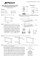
Step 1:
Fig. 2
Fig. 1
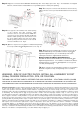
Step 3:
Fig. 3
Step 4: Attach top and bottom rails to deck posts (Fig. 4) and drill 1/4" hole in deck posts for wire (Fig. 5).
Fig. 4 Fig. 5
Step 5: Reinstall screw covers previously removed in Step 3 above and feed wire through post and across top rail connectors. Fig. 6
Important - Screw Cover Installation -
Step 2: Cut top and bottom rails to length, allowing for rail mounts of
fit and size. Place rails face to face. Starting from the center of the
rails, mark 4 1/8" on center. Fig. 2
The T2 screw cover must be properly installed for the system to work.
Improper installation of the screw cover will prevent the pierce connectors
from making electrical contact with the wire. Elimination of this critical part
from the assembly could result in an electrical short should the pierce
connectors contact the metal head of the screw. The T2 screw cover is
intended to be installed with the hollow center facing the screw head (see
Ill. A). The opposite side of the cover forms the seat for the pierce
connectors to contact the wire (see Ill. B). The side that faces the baluster
has a raised center and raised outer edge, forming a channel between the
inside and outside edge. The T2 screw cover fits snugly when aligned and
pressed into place. Access to the mounting screw for replacement of
damaged rails or balusters will require the removal of the T2 screw cover.
Measure rails from post to post. Fig. 1
For Lighted Baluster Models 171-Series
Lighted Baluster Installation Instructions
For Use With Landscape Lighting Systems Only
Deck Impressions
Parts Diagram
Read and Save These Instructions
Outdoor Use Only
Ill. B (Faces wire)
Fig. 3A Fig. 3B Fig. 3C
Ill. A (Covers screw head)
Fig. 6
from the top rail connector and remove top rail connector
from baluster (Fig. 3A). Using one of the provided
mounting screws, push the pointed end of the screw
through the hole in the back side of the rail connector to
pop out the plastic screw head cover (Fig. 3B). The
bottom rail connector can be removed from the opposite
end of the lighted baluster by sliding the connector sleeve
up the baluster (Fig. 3C). Attach baluster rail connectors
to the top and bottom rails using the screws provided. For
non-lighted balusters, use accessory Deck Impressions
mounting hardware 171-7620 (sold separately). Fig. 3
For lighted balusters, unscrew the rail connector sleeve
T2 - screw cover
T4 - threaded collar
B2 - bottom sleeve
T1 - top rail connector
T3 - pierce connector
B1 - bottom rail connector