
Installation Guide


Insert
Rail
Cap Rail
Angle adaptor wedges are available for 22.5˚ and 45˚ rail angles. Important: the holes in
the angle adaptor wedges line up with the stair rail connectors (sold separately).
If installing a 22.5˚ angle railing, attach the stair connectors and wedges centered
on the posts. If installing a 45˚ angle railing, attach the 45˚ adaptor wedges
centered on the posts. Attach stair connectors to the 45˚ using the provided
screws.
Measure the distance between the installed angle connectors to determine the length
of the top and bottom rails. Cut the top and bottom rails to length.
Step 7 Determine the spacing of the balusters.
Classic, Estate and balusters The rails are pre-drilled with the proper
spacing. Attach baluster connectors to the top and bottom rails. Do not over-tighten
screws. Apply silicone caulk on each connector to prevent balusters from turning or
rattling after installation is complete. The caulk should be on the outside of the round
connector, and on the inside of the designer baluster connectors.
NOTE: Use screws
(self tapping) that are included with rail kit for Classic, Estate and Twist Balusters. DO NOT
USE screw included with baluster connectors.
Ellipse balusters Both top and bottom rails will be installed with the pre-drilled
holes facing down to prevent water from collecting in the rail. 4-1/4" on-center and
equal spacing for the end spacing. Start by finding the center of the rail. Rail length
÷ 2 = center of rail. Mark every 4-1/4" from the center line to each end. This will
leave the end spacing 4" or less on both ends and require 3 Ellipse balusters per
foot. Attach connectors to both rails on marked locations.
s. NOTE: Use screws (self tap-
ping) that are included with rail kit for Classic, Estate and Twist Balusters. DO NOT USE screw
included with baluster connectors.
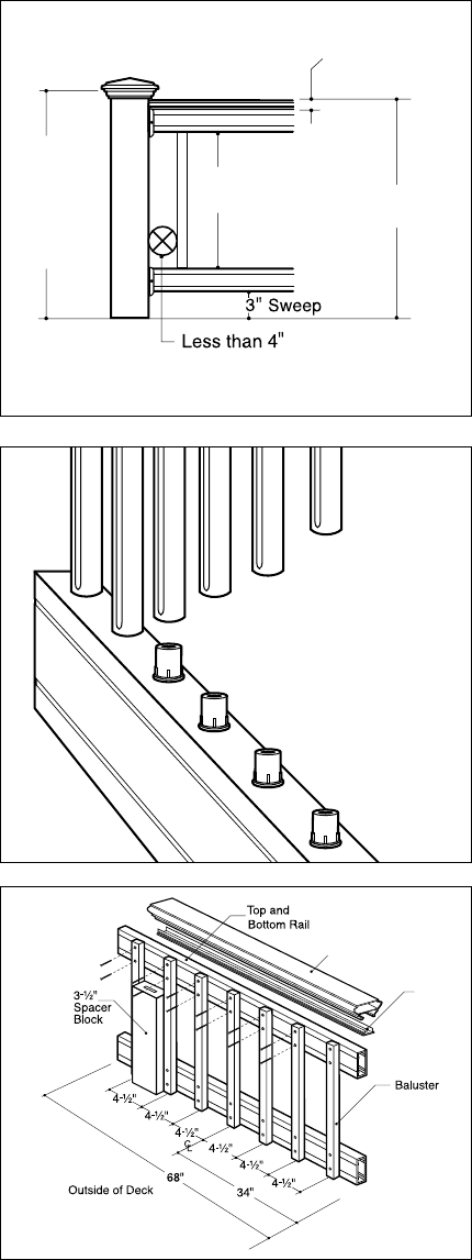
Traditional, Baroque and Arc balusters Both top and bottom rails will be
installed with the pre-drilled holes facing down to prevent water from collecting in
the rail. Maximum 4-1/2" on-center and equal spacing for the end spacing. Start
by finding the center of the rail. Rail length ÷ 2 = center of rail. Start the first aluminum
baluster on-center of the center line. Mark every 4-1/2" from this line to each end.
This will leave the end spacing less than 4" on both ends and require 2.5 aluminum
balusters per foot (fig. 4). Tip: Use a piece of 2x4 (3-1/2" actual) as a spacer block
for the spacing between balusters.
Glass balusters Both top and bottom rails will be installed with the pre-drilled holes
facing down to prevent water from collecting in the rail. 7-1/2" on-center and equal
spacing for the end spacing. Start by finding the center of the rail. Rail length ÷ 2 =
center of rail. Start the first glass baluster on-center of the center line. Mark every 7-1/2"
from the center line to each end. This will leave the end spacing 4" or less on both ends
and require 1.5 glass balusters per foot. If installing using connectors, attach connectors
to both rails on marked locations. Tip: If face-mounting to rail, use a piece of 2x4 (3-1/2"
actual) as a spacer block for the spacing between balusters (fig. 5).
Step 8 Position the bottom rail between posts and center. Note: Check building code
requirements for maximum spacing between deck surface and bottom of rail (sweep).
Spacing of 3" is recommended, but can be more or less if codes allow (fig. 3). Mark
the location of the bracket on both posts. Remove rail. Mark the screw locations and
pre-drill through the post sleeve only, using a 1/4" drill bit. Attach each bracket to the
post with two 2" screws.
Step 9 A support block is needed at the center of each rail. Cut the support block to
the proper height. Attach to the bottom of the lower rail (refer to fig. 1). Find the center
of the rail and pre-drill using a 1/8" drill bit. Attach the support block connector using the
included screw. Mark the location of the support block on the deck surface and attach the
other support block connector to the deck using the included screw. Install the bottom
rail between the posts. Using the brackets as a guide, pre-drill each screw hole using
a 1/8" drill bit and attach each end to brackets using two 1" screws. Tip: Use a driver
extension bit to avoid marring the rail or post sleeve with the drill chuck.
Step 10 Figure 3 illustrates how a 36"-high railing might be sized. Note: Use a fixture
to ensure a consistent length (+/- 1/16").
Classic, Estate and Glass balusters using
connectors Attach balusters to the lower rail by sliding onto connectors (fig. 4).
Step 11 Position the top rail between the posts. Check for level end-to-end and vertically.
Mark the bracket location on post sleeve and remove rail. Mark the screw locations using
the bracket as a guide, and pre-drill using a 1/4" drill bit through the post sleeve only. Attach
bracket to the post with two 2" screws at one end. Repeat for the other end.
Classic, Estate, balusters and Glass balusters using
connectors Lower the top rail into position, placing the balusters onto the connectors
while working from one end of the railing to the other. Tap with a rubber mallet if
needed to eliminate any gaps. Attach the rail to each bracket by pre-drilling with a
1/8" drill bit and using three 1" screws. Tip: Use a driver extension bit to avoid marring
the rail or post sleeve with the drill chuck.
37-
1
/2" Rail
Height
39"
Post
Sleeve
Height
(Rail
Height
plus 1-
1
/2")
26" Baluster
Height
1-
1
/
2
"
Cap Rail
fig. 3
fig. 4
fig. 5