
Installation Guide


POST MOUNT INSTALLATION INSTRUCTIONS
Deck Mount Kit (sold separately) includes (1) 8 hole bottom base plate, (1) 4 hole surface plate, (4)
6" mounting bolts and (4) 5/16" leveling screws. Note: Max allowable rail span is governed by rail
manufacturer.
THE DIAGRAMS AND INSTRUCTIONS IN THIS BROCHURE ARE FOR ILLUSTRATION PURPOSES ONLY AND ARE NOT MEANT TO REPLACE A LICENSED PROFESSIONAL. ANY CONSTRUCTION OR USE
OF THE PRODUCT MUST BE IN ACCORDANCE WITH ALL LOCAL ZONING AND/OR BUILDING CODES. THE CONSUMER ASSUMES ALL RISKS AND LIABILITY ASSOCIATED WITH THE CONSTRUCTION
OR USE OF THIS PRODUCT. THE CONSUMER OR CONTRACTOR SHOULD TAKE ALL NECESSARY STEPS TO ENSURE THE SAFETY OF EVERYONE INVOLVED IN THE PROJECT, INCLUDING, BUT NOT
LIMITED TO, WEARING THE APPROPRIATE SAFETY EQUIPMENT. EXCEPT AS CONTAINED IN THE WRITTEN LIMITED WARRANTY, THE WARRANTOR DOES NOT PROVIDE ANY OTHER WARRANTY,
EITHER EXPRESS OR IMPLIED, AND SHALL NOT BE LIABLE FOR ANY DAMAGES, INCLUDING CONSEQUENTIAL DAMAGES.
©2019 Universal Forest Products, Inc. All rights reserved.
10771 9/19
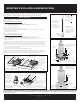
6"adjustable top block for
36" & 42" railing heights
Note: For 42" rail
applications, remove
the adjustable top
block, flip it over and
reattach.
fig. 3
The innovative block
design that offers a
better, more reliable
and secure mounting
platform for your
fasteners.
Installation Options
Option 1 - Deck Mount Kit Installation: Fig. 2 and Fig. 4 with bolts and steel bottom base plate
• Residential applications only
• Flange Mount: Up to 42" height
• Requires double 2" x 8" on the flat blocking
• Covered under CCRR-0257
Option 2 - Concrete Installation: Fig. 5
• Flange Mount: Up to 42" height
• Use minimum diameter 3/8" masonry fastener (length and type to be determined by the installer)
• Covered under CCRR-0257
Option 3 - Lag Bolt Installation: Fig 1
• Residential applications only
• Flange Mount: Up to 36" x 6' rail span
• Requires triple 2" x 8" on the flat blocking
• Use 1/2" x 6" lag bolts installed with impact driver (sold separately)
It is the responsibility of the installer to meet all code and safety requirements, and to obtain all
required building permits. The deck and railing installer should determine and implement appropriate
installation techniques for each installation situation. Universal Forest Products, Inc. shall not be held
liable for improper or unsafe installations.
1. Plumb post with level and shim between the deck and post-mount base plate, if necessary.
2. Installers must determine the proper mounting hardware.
Note: For use with composite post sleeves, raise the post sleeve 3/8" off the deck so composite
sleeve can move with the post mount. Base trim will cover any gaps from decking.
fig. 4
3x8" Hex Head Bolt
Grade 5
Washer
Deck
Leveling Screws
Leveling Shim
Double 2" x 8"
Wood Support
fig. 5
Nut
Leveling Shim
Washer
Nut
Washer
3/8" diameter
masonry hardware
Joist Block
Triple 2" x 8"
Laid Flat*
Outer Rim Joist
Joist
Triple 2" x 8"
Laid Flat*
Joist Block
Side Rim Joist
View of post mount
base, Surface and
Bottom Plates, and
hardware kit for
wood mounting kit
(sold separately)
fig. 1
fig. 2
Bottom Plate and 3/8" Nuts
with Washer attached under double
2" x 8" wood mounting blocks
#10 x 3" deck screws to
attach Mounting Blocks to
side rim joist and stringers
Double 2" x 8" Mounting
Block under Decking**
* Triple 2" x 8" Laid Flat for Lag Bolt Installation
#10 x 3" deck
screws to attach
Mounting Blocks
to side rim joist
and stringers
** Double 2" x 8" Laid Flat for Bolt/Plate Installation
Bottom Plate
Surface Plate
Surface Plate
Proper type, length and
installation of masonry
fasteners to be determined
by the installer