
Installation Guide

The appearance of slotted composite decking
changes when viewed from different ends. To
achieve the most consistent color, install all
of the boards in the same direction using the
product end tags (A) as a point of reference.
Installing boards in opposing directions will
create contrasting light and dark shades of
the deck board color and is not covered under
warranty.
Prior to construction, check with your local
regulatory agency for special code require-
ments in your area. For best results, follow
these simple installation instructions, paying
close attention to gapping, spacing and
fastener requirements.
Joist span:
Depending
on local building code requirements, refer to
ESR-1573 or CCMC 13378-R for joist spac-
ing and stair tread support options. Contact
product support at 877-463-8379 for informa-
tion on commercial applications.
Side gapping:
1/4".
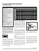
End-to-end spacing:
Allow
a minimum of 1/16" gap between board ends
for every 11° C of difference between instal-
lation temperature and the hottest temperature
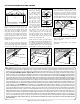
expected (figure 1). For any decking where two
boards meet end-to-end over a joist, add addi-
tional blocking (figure 2). Allow 1/4" distance
between all decking material and any perma-
nent structure or post. After all of the decking
has been attached, snap a chalk line (white or
yellow chalk recommended) flush with or up to
1-1/2" out from the deck framing and trim with
a circular saw.
All wood and composite decking products
require proper ventilation and drainage to
ensure their longevity. When using a minimum
2x6 joist standing on edge and the suggested
1/4" side gap, there should be a 2" clear
space between the bottom edge of the joists
and grade in order to allow for proper ventila-
tion. Adequate drainage is also needed to
prevent water from pooling under the deck.
Fasteners
Fasteners should fits into the slot on each side
of the deck board to eliminate pre-drilling and
provide a timeless, fastener-free deck surface.
The deck boards require traditional fasteners
on the outside and inside edges of the deck.
Begin by fastening the outside edge of the first
board to the rim at every joist. For this, we
recommend using 2-1/2" corrosion-resistant,
composite wood deck screws. These screws
help minimize the common “mushroom” effect
that sometimes occurs when using standard
fasteners. It can also reduce the amount of
pre-drilling and countersinking.
If using ordinary coarse-thread deck screws,
always pre-drill a pilot hole and countersink
prior to driving screws. Screws should be
driven flush with the surface. Do not over-
tighten. Use one fastener per board at every
joist. For any decking where two boards meet
end-to-end over a joist, add additional
blocking. Always pre-drill a pilot hole when
fastening within 1-1/2" of board ends, whether
using composite or wood screws. Do not over-
tighten screws at board ends.
Fasten the outside edge of the first board to the rim
joist with screws. Pre-drill and countersink all deck
screws, regardless of type, that are within 1-1/2" of
the end of the deck board. On the other side of the
board, place a hidden fastener into the slot and center
on the joist.
Notice to installers
• 305 stainless steel, black head screws
• DO NOT use cordless impact drivers
• Set drill speed 1500-1750 RPM
• Max torque not to exceed 23 inch pounds
• Pre-drill knots or dense hardwood
Always wear safety glasses when using
power tools.
Items you will need
• Drill/power screwdriver
• 1/8" drill bit
• Circular saw with carbide-tip blade
• Assorted fasteners (see instructions)
• Tape measure
• Carpenter’s pencil
• Safety glasses/goggles
Coverage
87 pieces of hidden fasteners will install:
• 50 sq. ft. of 6" wide (5-1/2" actual)
deck boards on 16" centers, or
• 43 sq. ft. of 6" wide (5-1/2" actual)
deck boards on 12" centers
(A) end tag
5/4x6-16' GR.
TIPS FOR SLOTTED DECKING INSTALLATION
USING HIDDEN FASTENERS
Board end to board end gapping requirements
Warmest annual temperature °C expected in region
°C -7 -1 4 10 16 21 27 32 38 43 49
-7 1/8 1/8 1/8 1/8 1/8 3/16 3/16 1/4 1/4 5/16 5/16
-1 1/8 1/8 1/8 1/8 1/8 3/16 3/16 1/4 1/4 5/16
4 1/8 1/8 1/8 1/8 1/8 3/16 3/16 1/4 1/4
10 1/8 1/8 1/8 1/8 1/8 3/16 3/16 1/4
16 1/8 1/8 1/8 1/8 1/8 3/16 3/16
21 1/8 1/8 1/8 1/8 1/8 3/16
27 1/8 1/8 1/8 1/8 1/8
32 1/8 1/8 1/8 1/8
38 1/8 1/8 1/8
43 1/8 1/8
49 1/8
Temperature °C on day of installation
figure 1
continued on reverse
figure 2