
Installation Guide
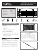

Step 1 Determine the layout and number of railing posts needed for your
deck. Post spacing is 6’ or 8’ on-center. Cable posts are available pre-
drilled for end, line and corner posts. Cable is available in lengths of 5’, 10’,
15’, 20’, 25’, 30’, 40’ and 50’. Many layout options are possible. One tip is
to start with the most visible run. It’s the one on which you want the least
interference with the view, so you can start from there and build around it.
Corner applications: When taking cable through a corner, do not bend the
cable past 45˚ at any time. When turning 90˚, use a corner post (fig. 2b) or
make a 2-step turn using a double corner post configuration (fig. 4), or stop
the cable run and start a new run. Example: A 12’ x 16’ deck attached to
a building with a 4’ access opening on one side will require a total of nine
posts (eight if using corner post).
Once the layout is determined, all posts, rails and spacers are installed prior
to the cable.
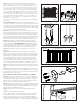
Step 2 Installing Posts: Install posts by attaching the aluminum base to
the surface of the deck. Position the post so the fastener will go into the floor
joist, and make sure the decking is firmly attached to the joist at the location
of the posts. Proper structural blocking/ framing under the decking material
is required when attaching the post to a wood frame deck because decking
alone is not approved as structural framing (fig. 5).
Step 3 Ensure the end, line and corner posts are used in the correct
location and oriented the proper way. The larger diameter hole on the end
posts should face away from the cable run. Position the post assembly onto
the location where it will attach to the deck. Four 3/8” diameter mounting
holes are provided on the base. When the final position is determined, mark
the base hole locations. Remove the post assembly and drill 15/64” holes in
the marked locations through the decking and into structural blocking.
Step 4 Reposition the post assembly with the leveling plate inserted
between the deck and the post base, and aligned with the predrilled holes.
Insert the post fasteners (NOT INCLUDED), and partially tighten. Using a
level, adjust the leveling set screws with a 3/16” allen wrench until the post
is plumb. Fully tighten the post fasteners to secure the base to the deck
structure. Note: Recommended 5/16” x 4” or longer lag screws (fig. 6).
Step 5 Finish by sliding a post base trim (optional) over each post for a
finished look.
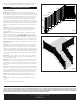
Step 6 Measure the distance between installed posts to determine the
length of the top rail. The rails are sized for 6’ and 8’ on-center posts, when
using 2.5” posts, and include space for the brackets. Position rail adjacent
to installed posts. The distance between the post and the spacer should
be equal on both ends. Use one spacer for 6’ rails and two for 8’. Never
span more than 36” without a spacer to maintain proper cable spacing.
As needed, trim the top rail to length for runs that are less than 6’ or 8’ on-
center. Mark the length on top rail, and remove an additional 1/2” from both
ends (1” overall) for the bracket to fit between the rail and post (fig. 8).
Step 7 Place the brackets on ends of the rail. Attach the brackets to the rail
with a screw attached through back of bracket into each internal screw boss
(fig. 9).
Step 8 The finished rail height is typically a minimum of 36” or 42”. Using
the cable spacer, prop rail in place and level. Mark the bracket holes on both
posts. Remove rail. Predrill screw locations through the posts, using a 3/16”
drill bit at top bracket locations (fig. 10).
STOP – Make sure post base trim is installed before continuing.
Step 9 A cable spacer is needed at least every 3 feet (1 is included in the 6ft
kit, 2 in the 8ft kit). Attach spacer connectors to the bottom of the top rail.
Predrill using a 1/8” drill bit. Attach the spacers to the spacer connectors.
Mark the location of the spacer on the deck surface and attach the other
spacer connector to the deck using the included screw.
Step 10 Position the rail between the posts. Check for level end-to-end and
vertically. Attach brackets to the post at one end. Repeat for the other end.
Tip: Use a driver extension bit to avoid marring the rail with the drill chuck.
Install all rails prior to installing cable (fig. 10).
Step 11 Set post caps on each post. Gently tap with rubber mallet to
secure.
Install cable according to the cable instructions.
Tips for cable corner post. The cable corner post comes with an insert to
feed the cable around the corner without binding and plastic threading
needles. Ensure the insert is in the correct corner. Place the threading
needle on the cable and push it onto the end to lock in place. Thread the
needle through the corner. Make sure to push and pull the cable at the same
fig. 6
fig. 9
fig. 7
fig. 10
Additional
Wood Blocking
•
fig. 5
Subtract 0.5”
Distance between posts
Subtract 0.5”
fig. 8
fig. 4