
Specifications

DeCrane Aerospace Audio International DVD-5x2-01-x Installation & Operation Manual
Document # 540356, Rev C, 12/2008
Page 14 of 38
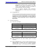
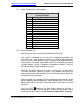
3.9 Pinout Assignment and Descriptions
DVD-5x2-01-x
J1 and J2 Pinouts
Pin #
Description
1 + 28 VDC Power Input
2 Ground
3 R+ Audio Output
4 R- Audio Output
5 L+ Audio Output
6 L- Audio Output
7 RS485 Data Bus A (HI)
8 RS485 Data Bus B (LO)
9 Infrared Digital Input +
10 Infrared Digital Input -
11 ID Strap 2
12 ID Strap 3
13 ID Strap 4
14 ID Strap Common
15 “Pause Mode” Constant GND Input
3.10 Post Installation Test
Note that these steps should be taken with both DVD drives.
This section is designed to assist the user in determining whether the
DVD Player has been properly installed. First, before applying power,
ensure the unit is connected correctly, especially concerning Power and
Ground wiring. The audio signal output of the unit is generally connected
to cabin speaker systems in addition to headphone locations. Verify all
connections before supplying power to the unit.
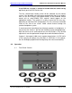
There are no ON/OFF controls on the unit so ensure that +28 VDC power
has been connected. Normally if power is not properly connected, the
front panel controls’ backlighting will not be illuminated and the player will
not respond to any commands.
Activate monitors and speakers from the appropriate control panels. Audio
will be supplied through headphones and/or speakers per system design.
Make certain that the monitor(s) connected to the DVD Player are on and
functional.
Press the EJECT button on the Front Panel Controls or by using a
remote control device. The disk will eject. Carefully slide and load a clean,
functional DVD disc into the slot. Be certain to load the disc correctly—