Setup Guide
Contents Introduction Introduction 1 • Important Safeguards 3 • Installing Digital Sprite 2 5 • Quick Install 6 • Connecting External Devices 8 • Configuring Digital Sprite 2 15 - Using the Menus 15 - Time, Date & Language 17 - Camera Viewing 18 - Schedule 19 - Standard Recording Schedule 20 - Variable Recording Schedule 23 - Network Options 24 - Alarm Options 27 - VMD Options 33 - Display Options 34 - Passwords 36 - System Options 37 - Record Options
ENGLISH A digital video recorder • Playback and record simultaneously, without affecting recording. • 31 days or more of 24 hour time-lapse recordings in one box*. • Instant access to images recorded on the hard disk with no tapes. *Refers to the 320GB (or higher) model. Network transmission • • • • • • Web configuration in conjunction with on screen menus. View live and playback images across the network. Remote reporting for centralised monitoring. FTP, SMTP support for remote download of images.
Important Safeguards Record audio in real time Remote keyboard control (optional) Remote keyboard compatible Control of multiple units Telemetry controller Network viewing Live viewing Playback viewing Multiple simultaneous Users Telemetry control Copy images across networks E-mail on event activation Storage devices RAID & JBOD Plextor CDR (check for compatible models) 1.
ENGLISH LIGHTNING STRIKE The Digital Sprite 2 range has some inbuilt protection for lightning strike, however it is recommended that isolation transformers be fitted to the system in areas where lightning is a common occurs. REGULATORY NOTES FCC AND DOC INFORMATION (USA and Canadian Models Only) WARNING: This equipment has been tested and found to comply with the limits for a Class A digital device, pursuant to part 15 of the FCC rules.
Installing the Digital Sprite 2 Check the contents of the box: Digital Sprite 2 IR remote handset Mains cable with three pin plug fitted (North America) Mains cable with plug fitted (European) Mains cable without plug fitted (other regions) Rack mount kit (rack mount ears, rear supports, and fixing screws) 485-bus cable Setup Guide and Operator Guide, note the Networking Guide is stored on the unit and downloadable from the Web interface Choosing a location for installation Digital Sprite
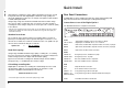
ENGLISH Quick Install With analogue recording, the image quality is dependent on the type of VCR being used; VHS or S-VHS. Digital Sprite 2 allows the image quality to be altered by adjusting the image size, for example, low quality is 14KB, medium is 18KB, and high is 25KB*. Using a larger image size will fill the hard disk faster than a smaller image size, as more space is required to store it.
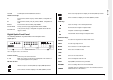
2x MMJ ports for DM 485-BUS accessories. ENGLISH 485 BUS Show a four way split screen display on the Main (MON A) monitor. Alarms and relays Screw terminal, alarm relay dry contact, NO/NC, configurable for alarm. Screw terminal, activity relay dry contact, NO/NC, configurable for VMD. R1 R2 Show a multiscreen display on the Main (MON A) monitor. VCR Keys Pause the image in Live and Playback mode. DIRECT Screw terminal, direct auxiliary input, NO/NC.
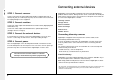
ENGLISH Connecting external devices STEP 1. Connect cameras Connect cameras to the video inputs marked VID1 to VID6 (6-Way unit), to VID9 (9-way unit) or to VID16 (16-way unit). Use the bottom row of connectors for looping through to other equipment. Digital Sprite 2 uses 485-Bus networking to interconnect Dedicated Micros products and accessories. Storage devices can be connected to the SCSI port, and telemetry cameras can be connected to the serial ports.
Digital Sprite 2 currently supports a number of PTZ / dome protocols using serial telemetry, as well as various RS232 matrix protocols. Serial telemetry requires a twisted-pair connection from the Digital Sprite 2’s serial port to the dome. Serial telemetry can be either star configured (from the Digital Sprite 2 serial port to each receiver), or delta configured (each receiver are linked (looped) together), or a combination of the two.
ENGLISH Connecting storage devices 2. JBOD Images are recorded to the internal hard disk for instant playback and searching by the operator. The capacity of the internal disk affects the amount of images and time that can be recorded. For example, a 80GB Digital Sprite 2 can record for 8 days at default record rates, but a 320GB Digital Sprite 2 can record for 31 days at the same record rates.
Digital Sprite 2 includes an enhanced video server allowing remote connectivity across an Ethernet network. Multiple users can connect simultaneously to the Digital Sprite 2 to view and control live or recorded video, download recorded images or review database details. The Digital Sprite 2 can be connected to a standard 10/100-baseT Ethernet network and using the viewing application offers full control of the unit from a remote location.
ENGLISH Viewing images across the network using a web browser Connecting Audio devices It is possible to use Microsoft Internet Explorer (version 6.X and above) and Netscape Navigator (version 7.1 and above) to view images from a Digital Sprite 2. Follow the previous instructions to display the Digital Sprite 2 web page, but click on the ‘Live’ option instead of the ‘Software’ option.
Connecting alarm inputs The Digital Sprite 2 supports up to 18 on-board alarm connections. By default inputs 1 to 16 are configured to trigger event recording on cameras 1 to 16 of a sixteen channel unit. There is an additional alarm, and a direct alarm.
ENGLISH Connecting additional alarm modules Optional alarm modules (DM/CI01) can be added to the Digital Sprite 2 to increase the number of alarm inputs. The Digital Sprite 2 can support multiple alarm modules connected to the 485-bus. To add alarms: 1. Connect the corresponding alarm contact to the alarm input, i.e. Alarm 2 would be connected between ground (GND) and A2. 2. If multiple alarm modules are required then each will need to be addressed; consult the alarm module documentation for details. 3.
Configuring the Digital Sprite 2 Using the menus Video switchers allow multiple Digital Sprites to be controlled from a single pair of monitors. This allows the flexibility of controlling up to 256 cameras from a single location without having to purchase extra matrix equipment. The Video Switcher routes the monitors from the Digital Sprite 2 being controlled to the operator’s monitors. Up to 16 control positions can have monitor switching.
ENGLISH Navigating a menu Example of using the menu to change the time: The menus are displayed with options on the left-hand column and settings in the right hand column. A cursor (highlighted text) can be moved using the cursor keys on the front panel, or the joystick on the optional remote keyboard. 1. Press and hold the Menu key to enter the installer menu. The ‘Time, Date & Language’ page is displayed.
Time, Date & Language ENGLISH 4. Use the button to change the settings, in this example 15:45.
ENGLISH Camera Viewing System Shutdown Camera Viewing View The Digital Sprite 2 can be shutdown from this menu. Some menu changes would require the unit to be reset, for example changes within the System Features menu. To reset the Digital Sprite: 1. Use the key to highlight the ‘System Shutdown’ option. 2. Select Enable, a prompt will be displayed. 3. Press and hold the Camera 1 key for 5 seconds. The unit will shutdown, where a prompt will appear to say you can switch the unit off.
Schedule Schedule Schedule Type Timed Zone Control, Timed Night On On Between, 7 Day Timer, Off, On Weekend Off On Between, Off ENGLISH A schedule can be used to record selected cameras at different times, change the record rates and determine whether alarms or activity is enabled. 7 Day Timer This sub-menu allows a schedule to be independently set for each day of the week.
ENGLISH Standard Recording Schedule Keyswitch The input which activates the keyswitch can be configured for one of the following options: • None - There is no keyswitch operation enabled. • Direct - The direct input on the rear panel has been allocated as the keyswitch trigger. • Aux - The Aux input on the rear panel has been allocated as the keyswitch trigger, select a contact. • Module 01 - Module 16 - select any input on any module to be the keyswitch trigger.
ENGLISH Standard and Event PPS Events Active Select a record rate in pictures per second (PPS) to be recorded across all enabled cameras. The Standard Record rate will be the number of PPS recorded when the unit is in non-alarm mode. The unit will switch to the Alarm rate when an alarm is triggered. Note: The maximum record rate is 25PPS/30PPS (PAL/NTSC) for a single camera. The default record rate is 6PPS (00167 ms), which is equivalent to a VCR in 24-hour time lapse mode.
ENGLISH • Interleaved – This will set the Digital Sprite 2 to record the alarm cameras more frequently than non-alarm cameras, by interleaving the two i.e. if camera 1 is in alarm the interleave recording would be 1213141516... Note: By using event interleave, it is possible to keep the record rate constant but effectively increase the speed of alarm or activity recording. Image size The image size determines the quality of the image that is recorded to disc.
Variable Recording Schedule Variable Recording Camera Units Camera 01 PPS Day Night Weekend Record Operation Off Variable Standard Record rate N/A 006 N/A N/A, 000 - 025 Alarm rate N/A 006 N/A N/A, 000 - 025 Pre-alarm rate N/A 006 N/A N/A, 000 - 025 Pre-alarm Pics N/A 014 N/A Pre-alarm buffer use N/A 014% N/A Off, Standard, Variable, Both Note: The variable record rate is camera specific and applies to the camera being configured.
ENGLISH Network Options This option allows you to allocate properties to the Network connection of the Digital Sprite 2. Network Options Disabled, Enabled DHCP Disabled TCP/IP address 172.016.080.007 Sub net mask 255.255.000.000 Default gateway 000.000.000.
Every network has a different MTU, which is set by the Network Administrator. Ideally, the MTU should be the same as the smallest MTU of all the networks between your machine and the final destination. If the MTU figure is too large they will be broken up (fragmented), which slows down transmission speeds, and in some cases cause a ‘Connection to Unit Timed Out’ message when using DM Network Viewing Software.
ENGLISH PPP Selection Secondary DNS PPP IP 010.001.001.241 Disabled, Enabled PPP idle line timeout 180 Seconds 000 - 500 Seconds PPP link down timer 02 Minutes 00 - 60 Minutes PPP IP Enter the IP address allocated to the PPP functionality. Use the buttons to scroll through the available numbers. Remote Reporting and PPP Idle Line Timeout This is the time the Digital Sprite 2 will wait before disconnecting the PPP link if no data is being transmitted or received.
Alarm Options The Digital Sprite 2 supports enhanced network features, the firewall option adds security to the system. It ensures only authorised users gain access to the Digital Sprite 2 by utilising IP address and port filtering. Note: It is recommended that the Firewall Options feature be configured via the Web interface, refer to the Networking Guide for full configuration information.
ENGLISH Spot alarm display (MON B) Global alarm • Last - If a number of alarms are triggered at the same time, the last alarm image will be displayed on the monitor. • Sequence - This will display all alarm images in a sequence. These settings can be applied for alarm triggers, activity detection, both or alternatively the option can be disabled by selecting Off. It is possible to allocate Aux Relay 1 to trigger on receipt of any alarm.
Schedule Activation An alarm zone logically groups alarms and initiates actions when an alarm is activated. Each Alarm Zone can be individually configured within this menu. This allows the Operator to configure when an alarm will be active, i.e. active during Day and Weekend but inactive at Night. Move the cursor to the required setting and press the or to include or exclude from the Day, Night or Weekend options.
ENGLISH The Digital Sprite 2 places a ‘marker’ in the regular recording that acts as the start of the pre-alarm recording, the number of images available will be dependant on the pre-alarm time set. Note: If recording is not enabled there may not be any images on the disk. If pre-alarm recording is required, ensure recording is enabled. Alarm Duration This is the minimum time period in seconds from the start of the alarm that will be protected from being overwritten.
Zone Actions This identifies the actions that will be allocated to the zone being configured. Note: The actions are divided over three pages. Zone 01 Actions Page Page 1 Text Only Alarm Disabled Enabled Change Record Rate Both Standard, Variable, None Create Database Entry Enabled Disabled Connect on Alarm Enabled Disabled Archive Alarms Enabled Disabled Page This will scroll through all the available actions, there are three pages of actions. Use the buttons to scroll through the pages.
ENGLISH Close Relay It is possible to force a relay to close on receipt of an alarm trigger. The options available are: • Aux - The are six on-board relays any of these can be selected within this option. • Module 1 - An additional relay module can be connected via the 485 bus, one of the sixteen relays can be selected within this option. Record Still Images This will record a still image of the alarm camera along with the normal recording.
VMD Options General Contacts 1 2 >> Aux Aux Aux, Direct, 01 - 16 01 01 - 20 The Digital Sprite 2 supports Video Motion Detection and Activity Detection functionality, this menu allows the global parameters of this feature to be configured.
ENGLISH Display Options The Digital Sprite 2 places a ‘marker’ in the regular recording that acts as the start of the pre-alarm recording. The number of images available will be dependant on the pre-alarm time set. Note: If recording is not enabled, there may not be any images on the disk. If pre-alarm recording is required, ensure recording is enabled. Alarm Duration This is the minimum time period in seconds from the start of the VMD trigger that will be protected from being overwritten.
Display unit number It is possible to select the information that will be displayed on the Spot monitor. The options are: • None - switch all monitor text off (when used in conjunction with display unit number). • Clock only - display the time, date and mode of operation (Day, Night, Weekend and Spot). • Title only - display the camera number, the unit number, camera title and the mode of operation. • Both - display both the clock and title information.
ENGLISH Passwords The Digital Sprite 2 can be password protected to ensure only authorised personnel can gain access to the configuration menus of the system. Make a note of your passwords here: User / Playback password: .................................
System Options Unit number 01 System name DS2 Factory default Reset IR Receiver Enabled Audio Edit Serial & telem ports Edit System logs Edit Status page On 01 - 16 Enabled, Disabled Unit number When multiple units are connected together via the 485-bus, a unit number must be set to identify each unit. Note: Modifying the unit number will disable control via a remote keyboard. The new unit number should be selected to regain control of the unit.
ENGLISH Serial & Telemetry Ports This allows each serial port (Serial 1, 2, 3 (Bus A) and 4 (Bus B)) to be configured for a specific function. The Digital Sprite 2 supports a number of serial protocols, this menu allows the peripheral serial protocol to be selected.
Option Manufacturer Model BBV 485 BBV All models Dennard Dedicated Micros 2050, 2055 Ernitec Ernitec JVC ENGLISH The supported PTZ / Dome camera protocols are: System Logs There are a number of system logs supported on the Digital Sprite 2, these logs can be viewed and used for Administration purpose.
ENGLISH Record Options Record Options 0000 - 9999 Days Timed expiry 0000 Day(s) Disk configuration Edit Image protection Edit Archive on event Disabled Disabled, Enabled/Edit Record mode Standard loop Standard loop, Write once Schedule rates Enabled Disabled Record text in image Disabled Enabled Event database config Edit Enter the date and start time for the period containing the recorded images.
Note: A CD/DVD must be inserted in the writer if the archive destination is set to CD/DVD. Archiving on Event allows alarms and VMD events to be automatically copied to a remote FTP server or to a local CD/DVD writer.
ENGLISH Record Mode Write Once The record mode option allows the unit to be configured to either Standard Loop recording (default) or Write Once recording. The ‘Write Once’ submenu determines how the Digital Sprite 2 records images. Write Once Options Loop Record Mode This is the default setting for the Digital Sprite 2 and identifies how the unit stores images on the internal hard drives. The recorded images will be saved on the hard disk in a ‘loop’.
Current Number of Entries Write Once Last Reset This displays the time and date the Write Once process was last reset. This sets the maximum entries within the event database. Changing this will reset the event database and clear all previously stored events. This read only setting identifies the existing number of entries within the event database. Maximum Number of Entries Schedule Rates This option is enabled by default.
ENGLISH Camera Setup Camera Setup Camera video input Camera 1 - Detected Title Camera 1 Input termination On On, Off Camera type Colour Colour, Mono Colour adjust --------|------- Contrast adjust --------|------- Camera video input Connected Connected, Disconnected None None, Serial 1, Serial 2, Telemetry type Bus A, Bus B Telemetry Title Each camera can be allocated a title. Use the through the available characters.
Alarms and Presets Input Source Camera 1 - Detected Module /Aux 000 - 999 secs 005 secs Pulse extension ENGLISH Alarms and Preset Contact Input Source Preset > Aux -- N/O 000 > 01 01 N/C 001 > 02 02 N/C 002 > 03 04 N/O 003 > Aux -- N/O 000 > --- -- N/O 000 > --- -- N/O 000 Zone Input Camera XX The currently selected camera number is displayed, along with its status – detected or not detected.
ENGLISH Activity Camera Setup Activity Camera Setup Sensitivity Camera 1 Detection Off Schedule activation Edit Sensitivity Indoor high Activity grid Setup Activity test Walktest Actions Edit Advanced VMD zones Disabled Off, On Indoor high, Indoor low, Outdoor high, Outdoor low, Very Low Disabled, Enabled/Edit Camera Each camera can be individually configured. Select the camera by pressing the corresponding camera key.
ENGLISH When you enter the Activity Grid screen, a 16 x 16 grid will overlay the image. Edit the grid so that it covers the areas of the image that require monitoring for activity detection and remove the monitoring from the areas where there may be continuous movement (e.g. trees, bushes) causing false triggers. Each cell can be individually enabled or disabled with the Camera 1 button. Alternatively it is possible to latch the cursor and select a group of cells to enable / disable.
ENGLISH Report VMD Activity Email Image Resolution A VMD activity trigger can be reported via an telnet message. If this option is enabled, the ‘Remote Reporting’ settings must be correctly configured. This identifies the resolution of the snapshot that will be attached to the e-mail, the options are: • Thumbnail - Default. • Low Resolution. • Medium Resolution. • High Resolution. Note: The resolution selected is a global parameter and will be common to all Zone and VMD alarms.
This option allows the VMD Zone configuration options to be accessed. Camera 01 VMD Zones Zone 01 01 - 16 Zone 01 Mode Normal Normal, Last trigger, Static, Zone disabled Zone 01 pixel count 20% 02 - 100% Zone 01 pixel change 20% 02 - 100% Zone XX Pixel Change This setting is a percentage value of the overall change required in the greyscale to be included in the pixel count.
ENGLISH Text Insertion Setup VMD Test Once the VMD Camera Settings have been configured, it is possible to test the configuration. Note: VMD must be enabled on the selected camera for the Walktest option to selected. When Walktest is selected, a prompt will be displayed. Follow the on-screen instructions. Note: This menu is only displayed if ‘Text in Image’ has been enabled in the ‘Record Options’ menu.
Operating the Digital Sprite 2 A background can be applied to the text within the image. This is disabled by default. The options available are; Black or White. ENGLISH Text Background The illustration shows the front panel controls for the Digital Sprite 2. EVENT 1 2 3 4 5 6 7 8 9 10 11 12 13 14 15 16 MODE COPY MENU GOTO LIVE PLAY SPOT RECORD POWER / IR INDICATOR 16 Way model shown.
ENGLISH Tip: The images are updated in the background automatically when the time and date is adjusted. Selecting a camera will display that camera. Note: Tap the Mode key to exit playback mode. The Play LED will be off. Using the Event log Alarms and activity detection are tagged and stored in the event log for easy retrieval. Each event is labelled with event type (alarm or activity), the camera title, time, and date.
Filter from Select the time and date of the first event to be displayed. If there is no event at the selected time, the next nearest event is displayed. Filter to Select the time and date of the last event to be displayed. If there is no event at the selected time, the next nearest event is displayed. Viewing cameras on the Spot monitor To select control of the Spot monitor, press the Mode key (or Spot key on the remote keyboard).
ENGLISH 2. If images are to be copied to the internal CD/DVD writer, insert a blank CD-R or DVD-R into the CD/DVD writer drive and select the CD-R/DVD option. If the images are to be copied to an FTP Server, select the FTP option. All FTP settings must be configured in the ‘Record Options - Archive on Event’ Menu. 3. Use the cursor keys to change the time to copy To and From. 4. Tap the Menu key to display the following menu: CD/DVD FTP Disk Archive List 1.
ENGLISH Quad Press the QUAD key to switch to quad display. Press and hold the QUAD key to edit the display, use to select the segment, press the required camera key to fill that segment. It is possible to select Live, Play or Review images in each of the quad segments. With the segment selected pressing the camera to be viewed will display a live image, pressing the button will display a playback of the recorded camera, pressing again will switch the unit into Review mode. Press Menu to exit.
ENGLISH Appendix 1 Rack mounting kit Installation A rack mounting kit is supplied with this product. It is important to use this correctly. The kit contains: Before connecting cables to the back of the Digital Sprite 2; 1. Attach the rear supports to the rack. 2. Using the supplied screws, attach the rack mount ears to each side of the unit. 3. Position the unit on the rear supports. 4. Attach the rack mount ears to the front of the rack.
Appendix 2 ENGLISH Using the remote control The remote control included with the Digital Sprite 2 duplicates the front panel. See the operator card for details. To use the remote control, the ‘IR receiver’ option needs to be enabled in the ‘System Options’ menu page. UNIT SELECT MODE HOLD SPOT EVENT GOTO 1 2 3 4 5 6 7 8 9 10 11 12 13 14 15 16 The remote control provides the following functions: UNIT SELECT Press UNIT SELECT followed by a camera key to log onto another unit.
58 ENGLISH
Dedicated Micros Ltd. DM France Dedicated Micros Benelux Dedicated Micros USA. Dedicated Micros, Asia PTY Dedicated Micros (PMalta) Ltd. 11 Oak Street, Swinton, Manchester. M27 4FL, United Kingdom Tel: +44 (0) 161 727 3200 Fax: +44 (0) 161 727 3300 9-13 rue du Moulinet 75013 Paris France Tel : +33 (0) 1 45 81 99 99 Fax : +33 (0) 1 45 81 99 89 Joseph Chantraineplantsoen 1 3070 Kortenberg Belgium Tel : +32 2751 3480 Fax : +32 2751 3481 23456 Hawthorne Blvd.