
DS2 Setup Guide

Dedicated Micros ©2007
25
DS2
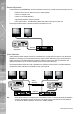
2. If multiple alarm modules are required then each will need to be addressed; consult the
alarm module documentation for details.
3. Connect the 485-bus cable from the alarm module to one of the 485-bus sockets on the
unit.
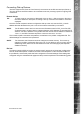
4. The polarity of the alarms (normally open/closed) is set in the ‘Alarms and Presets’ menu
page.
Note:
The alarm contacts do not have to correspond to the equivalent camera number, for
example alarm 2 could trigger camera 1, 2 and 3 into alarm mode, refer to Alarms and
Presets menu for conguration details.
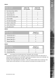
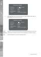
An alarm trigger can be programmed to perform any of the following:
Action
Close/Open Relay
Change the record Rate
Display the alarm camera on Main/Spot Monitor
Send a camera to a preset position
Menu page
Alarm Options
Alarm Options
Alarm Options
Alarms & Presets
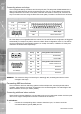
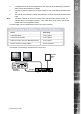
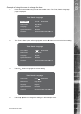
An example of connecting a remote alarm box to the unit.
485 bus
Remote
Keyboard
Remote
Alarm
Box
1 2 3 4 5 6 7 8
9 10 11 12 13 14 15 16
EVENT
GOTO
COPY
MENU
LIVE PLAY SPOT RECORD
MODE