www.dedicatedmicros.
CE NOTICE (EUROPEAN UNION). Marking by the symbol CE indicates compliance of this DM product (Dennard 2025 CCTV IR Lamp) to the Electromagnetic Compatibility Directive 89/336/EEC, and the Low Voltage Directive 73/23/EEC of the European Union. Such marking is indicative that this system meets the following technical standards. • • • • • • • EN 61000-6-3 EMC Standard Residential, Commercial and Light Industry.
1. Introduction Congratulations on choosing the Dennard 2025 infra-red LED illuminator. The product range is designed for high power and long life illumination for cameras with spectral responses extending into the infra-red range. With correct use the product will provide over 5 years of maintenance free operation. The unit comes with a dedicated power supply which requires a mains input. It must only be used with this supply. The illuminator and PSU are rated to IP66.
2.
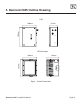
3. Dennard 2025 Outline Drawing PSU 200mm 300mm 117mm LED illuminator 184mm 258mm 208mm Fig. 1 – Outline Dimensions Dennard 2025 Installation Manual Page.
4. Components Supplied Before installation please remove the unit from the packaging and check that all items below have been supplied.
5. General Safety Information This Dennard 2025 equipment shall only be installed by qualified service personnel. The final installation must adhere to all national wiring regulations. The disconnect device must comply with IEC 60947. WARNINGS Read instructions before installing and power up. Instructions should be kept for future reference. If this unit shows signs of damage or malfunction, disconnect from mains immediately and contact Dedicated Micros. 6.
7. Mounting to a Dennard 2000 Pan and Tilt Unit Figures 2 and 3 show typical positions for I.R. illuminators when mounted to a remotely controlled Dennard 2000 pan and tilt head. Mount the Dennard 2025 illuminator using the M10 fixings supplied with the unit. Due to the weight of the Dennard 2025 it is not recommended that it is used with the optional side mounting plate on the pan and tilt unit. 8. Mounting to a wall The illuminator can be mounted directly to a wall to allow up and down adjustment only.
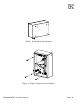
Fig. 2 – Two illuminator configuration with Dennard 2000 Pan and Tilt Unit Fig. 3 – Fixing Detail Fig. 4 – Mounting the Illuminator to a wall using the wall bracket Dennard 2025 Installation Manual Page.
Fig. 5 – Removing the sealing plugs Fig. 6 – Fitting the fixing screws and washers Dennard 2025 Installation Manual Page.
10. Wiring connections Electrical connections to the Dennard 2025 illuminator are made via terminal blocks inside the power supply unit. To access the connections remove the 4 cover screws on the power supply and remove the top cover. WARNING: Ensure the mains supply is isolated at all times whilst the cover is removed from the power supply. The mains supply should be fitted with a circuit breaker as a method of disconnecting the supply for maintenance.
The unit is supplied with a photocell connected and configured to switch the lamp on when light levels fall below 25 lux. If you want the lamp to run continuously or to use an alternative switching source please refer to the section ‘Remote Switch Inputs’.
CONNECTION TO CUSTOMER WIRING CONNECTION TO DENNARD 2025 PSU BROWN - LIVE 6mm STRIP AND PREP FOR TERMINAL BLOCK BROWN LIVE BLUE - NEUTRAL GREEN/YELLOW EARTH 4-6mm OUTER INSULATION DIAMETER 20mm MAX OUTER INSULATION REMOVED GREEN/YELLOW EARTH BLUE - NEUTRAL 24mm MIN Fig. 8 - Mains Cable Preparation 11. Configuration Power Settings It is possible to configure the supply at 4 different power levels. The factory setting is high power.
12. Control Settings The Denanrd 2025 illuminator can be switched from any one of three 12V switch inputs. The unit comes configured to use the photocell supplied which switches the lamp on at light levels below 25 lux. Using the Photocell The unit is supplied and configured to use a photocell located inside the power supply unit. The photocell relies on detecting ambient light to function correctly.
No..
13. Adjusting the Illuminator Angle Once you have completed the connections and have powered on the illuminator you will need to set the angle to get the best possible performance. • • • • View the area you wish to illuminate through a camera and monitor. If you are using the wall bracket then loosen the bolt on the bracket and move the illuminator so it is pointing towards the area you wish to see. Tighten the bolt.
14. Maintenance The only serviceable part in the illuminator assembly is the front window. This shall only be serviced by trained staff. No other parts of the unit are serviceable. The only serviceable parts inside the PSU are the fuses. Mains input fuse: This is identified as F1 on the label inside the PSU. This is a time lag (slow blow) fuse with 2A current rating, 250V rating and high breaking capacity. Illuminator output fuse: This is identified as F2.
15. Spares Parts and Accessories Part no. Description Dennard 95083 Replacement power supply unit Dennard 95084 Replacement illuminator unit 850nm/30 degree angle Dennard 94032 Photocell extension kit – kit to allow photocell to be mounted remotely from PSU Dennard 95086 Replacement window Dennard 95087 Replacement photocell 16.
17. Specifications Voltage Input: 100-240V~ 50-60Hz Power Input: 120W Mains input Fuse: 2A, time lag, high breaking capacity. Illuminator input fuse: 10A, time lag, high breaking capacity. IP Rating: B.S. EN 60529, IP 66 Other Approvals: EN 61000-6-3 EMC Standard Residential, Commercial and Light Industry. EN 61000-3-3 Limitations of voltage changes, fluctuations and flicker in public low-voltage supply systems for equipment with rated current up to 16A.
Notes
MANUEL D’INSTALLATION 2025
1. Introduction Nous vous félicitons d’avoir choisi le projecteur à DEL infrarouge Dennard 2025. La gamme de produits est conçue pour assurer une source d’éclairage haute puissance et de longue durée aux caméras à réponse spectrale s’étendant dans la zone infrarouge. Utilisé correctement, ce projecteur assurera un fonctionnement sans maintenance pendant 5 ans. Le projecteur est fourni avec un bloc d’alimentation électrique dédié qui requiert une alimentation secteur.
2.
3. Plan de forme Dennard 2025 Bloc d'alimentation électrique 200mm 300mm 117mm LED illuminator 184mm 258mm 208mm Fig.
4. Composants fournis Avant de procéder à l’installation, veuillez sortir le projecteur de l’emballage et vérifier que tous les éléments listés ci-dessous sont inclus.
5. Informations générales de sécurité Ce projecteur Dennard 2025 ne doit être installé que par des techniciens qualifiés. L’installation finale doit être conforme à la réglementation nationale en vigueur en matière de câblage. Le sectionneur doit être conforme à la norme IEC 60947. MISE EN GARDE Veuillez lire les instructions avant de procéder à l’installation et la mise sous tension. Conservez les instructions pour référence ultérieure.
7. Montage sur une caméra panoramique et inclinaison Dennard 2000 Les Figures 2 et 3 illustrent les positions typiques des projecteurs infrarouge lorsqu’ils sont montés sur une tête panoramique et inclinaison Dennard 2000 télécommandée. Montez le projecteur Dennard 2025 à l’aide des fixations M10 fournies avec le projecteur. En raison du poids du Dennard 2025, nous déconseillons son utilisation avec la plateforme de montage latérale en option de la caméra panoramique et inclinaison. 8.
Fig. 2 – Configuration à deux projecteurs avec caméra panoramique et inclinaison Dennard 2000 Fig. 3 – Détail de la fixation Fig.
Fig. 5 – Retrait des obturateurs Fig.
10. Raccordements de câbles Les raccordements électriques au projecteur Dennard 2025 s’effectuent au moyen de borniers situés à l’intérieur du bloc d’alimentation. Pour accéder aux raccordements retirez les 4 vis du capot du bloc s’alimentation et retirez le capot du dessus. MISE EN GARDE : Veillez à ce que l’alimentation secteur soit isolée à tout moment lorsque le capot est retiré du bloc d’alimentation.
Le projecteur est fourni avec une cellule photoélectrique raccordée et configurée pour que le projecteur s’allume lorsque le niveau d’éclairage baisse en dessous de 25 lux. Si vous voulez que le projecteur fonctionne continuellement ou utiliser une autre source de commutation, veuillez vous reporter à la section ‘Entrées de commutation à distance’.
RACCORDEMENT AU CABLAGE DU CLIENT RACCORDEMENT AU BLOC D’ALIMENTATION DU DENNARD 2025 6 mm DENUDER ET PREP. POUR BORNIER TERRE VERT/JAUNE MARRON SOUS TENSION BLEU - NEUTRE MARRON SOUS TENSION 4-6mm DIAMETRE ISOLATION EXTERIEURE TERRE VERT/JAUNE 20 mm MAX ISOLATION EXTERIEURE RETIREE BLEU - NEUTRE 24 mm MIN Fig. 8 - Préparation du câble d’alimentation secteur 11. Configuration Réglages de puissance Il est possible de configurer l’alimentation à 4 différents niveaux de puissance.
12. Réglages de commande Le projecteur Dennard 2025 peut être commuté à partir de l’une de trois entrées de commutation 12 V. Le projecteur est livré configuré pour utiliser la cellule photolélectrique fournie qui allume le projecteur à des niveaux de luminosité en dessous de 25 lux. Utilisation de la cellule photoélectrique Le projecteur est fourni et configuré pour utiliser une cellule photoélectrique située à l’intérieur du bloc d’alimentation.
No.
13. Réglage de l’angle du projecteur Une fois les raccordements effectués le projecteur mis sous tension, vous devrez régler l’angle pour assurer les performances optimales. • • • • Visualisez l’endroit que vous souhaitez éclairer sur une caméra ou écran. Si vous utilisez le support mural, desserrez alors le boulon sur le support et déplacez le projecteur de manière à le diriger vers la zone que vous souhaitez voir. Serrez le boulon.
14. Maintenance La seule pièce remplaçable du projecteur est la vitre avant. Ne confiez cette intervention qu’au le personnel ayant reçu la formation appropriée. Aucun autre composant du projecteur n’est remplaçable. Les seules pièces remplaçables à l’intérieur du bloc d’alimentation sont les fusibles. Fusible d’entrée d’alimentation secteur : Ce fusible est identifié F1 sur l’étiquette à l’intérieur du bloc d’alimentation. Ceci est un fusible à retardement de 2 A, 250 V et haute puissance de rupture.
15. Pièces de rechange et accessoires Pièce no. Désignation Dennard 95083 Bloc d’alimentation de rechange Dennard 95084 Projecteur de rechange 850 nm/angle de 30° Dennard 94032 Kit de rallonge de cellule photoélectrique – kit permettant de monter la cellule photoélectrique à distance du bloc d’alimentation Dennard 95086 Vitre de rechange Dennard 95087 Cellule photoélectrique de rechange 16. Dépannage MISE EN GARDE Débranchez de l’alimentation secteur avant de retirer le couvercle.
17. Caractéristiques Entrée de tension : 100 - 240 V~ 50 - 60 Hz Entrée d’alimentation : 120 W Fusible d’entrée d’alimentation secteur : 2 A, à retardement, haute puissance de rupture. Fusible d’entrée de projecteur : 10 A, à retardement, haute puissance de rupture. Indice IP : Norme B.S. EN 60529, IP 66 Autres homologations : EN 61000-6-3 Norme CEM Environnements résidentiels, commerciaux et de l’industrie légère.
Note
Note
MANUALE D'INSTALLAZIONE 2025
1. Introduzione Congratulazioni per aver scelto un proiettore a infrarossi Dennard 2025. La gamma di questi prodotti è progettata per l’illuminazione di elevata potenza e lunga resistenza delle videocamere con risposta spettrale che si estende alla gamma infrarossi. Se utilizzato correttamente, il prodotto può garantire 5 anni di funzionamento senza necessità di manutenzione. L’unità viene fornita con una linea di alimentazione dedicata che richiede un terminale di ingresso.
2.
3. Schema generale Dennard 2025 PSU 117 300 200 LED 184 258 208 Fig. 1 – Dimensioni schema Dennard 2025 Manuale d’installazione Pagina.
4. Componenti forniti Prima di procedere all’installazione, rimuovere l’unità dall’imballaggio e verificare che siano presenti tutti gli elementi elencati di seguito.
5. Informazioni generali sulla sicurezza L’apparecchio Dennard 2025 deve essere installato esclusivamente da personale qualificato. L’installazione finale deve essere conforme a tutte le normative nazionali in materia di cablaggio. Il dispositivo per la disconnessione deve essere conforme alla normativa IEC 60947. ATTENZIONE: Leggere attentamente le istruzioni prima di installare e accendere l’apparecchio. Conservare le istruzioni per riferimento futuro.
7. Montaggio su un’unità di panoramica e inclinazione di Dennard 2000 Le Figure 2 e 3 mostrano il posizionamento tipico dei proiettori a infrarossi, quando vengono montati su un gruppo di panoramica e inclinazione Dennard 2000 controllato remotamente. Montare il proiettore Dennard 2025 utilizzando i supporti di fissaggio M10 forniti con l’unità. Dato il peso dell’unità, non è consigliabile utilizzarla con la piastra di montaggio laterale opzionale sull’unità di panoramica e inclinazione. 8.
Fig. 2 – Configurazione dei due proiettori con l’unità di panoramica e inclinazione Dennard 2000 Fig. 3 – Dettaglio di fissaggio Fig. 4 – Montaggio del proiettore alla parete utilizzando l’apposito supporto Dennard 2025 Manuale d’installazione Pagina.
Fig. 5 – Rimozione delle spine per riempimento Fig. 6 – Montaggio delle viti e delle rondelle di fissaggio Dennard 2025 Manuale d’installazione Pagina.
10. Connessioni per il cablaggio I collegamenti elettrici al proiettore Dennard 2025 vengono realizzati attraverso le morsettiere collocate all’interno dell’unità di alimentazione. Per accedere ai collegamenti, rimuovere le 4 viti del coperchio dell’unità e il coperchio superiore. ATTENZIONE: Assicurarsi che la linea di alimentazione sia sempre isolata quando il coperchio viene staccato dalla stessa.
L’unità viene fornita con una fotocellula collegata e configurata per accendere la lampada quando il livello di illuminazione scende sotto i 25 lux. Se si desidera che la lampada funzioni ininterrottamente oppure si preferisce usare un’altra fonte di commutazione, fare riferimento alla sezione “Ingressi dei selettori remoti”. Inserire il cavo di alimentazione nel pressacavi e serrare con la fascetta stingicavi fornita.
CONNESSIONE AL CABLAGGIO DELL’UTENTE CONNESSIONE ALLA PSU DENNARD 2025 FASCETTE da 6 mm e PREDISPOSIZIONE PER MORSETTO MARRON E - FASE BLU - NEUTRO VERDE/GIALLO TERRA MARRONE FASE DIAMETRO DI ISOLAMENTO ESTERNO 4 - 6 mm VERDE/GIALLO TERRA MASSIMO ISOLAMENTO ESTERNO da 20 mm RIMOSSO BLU - NEUTRO MIN 24 mm Fig. 8 - Predisposizione del cavo di alimentazione 11. Configurazione Impostazioni per l’alimentazione È possibile configurare l’alimentazione su 4 livelli diversi.
12. Impostazioni dei tasti di comando Il proiettore Dennard 2025 può essere azionato da uno dei tre ingressi dei selettori da 12V. L’unità viene fornita configurata per l’utilizzo con la fotocellula fornita che accende la lampada ogni volta che il livello di illuminazione scende sotto i 25 lux. Utilizzo della fotocellula L’unità viene fornita configurata per l’utilizzo con la fotocellula collocata all’interno dell’unità di alimentazione.
N.
13. Regolazione dell’angolo del proiettore Dopo avere predisposto i collegamenti e acceso il proiettore, è necessario impostare l’angolo per ottenere le migliori prestazioni. • • • • Visualizzare l’area che si desidera illuminare attraverso la videocamera e il monitor. Se si utilizza il supporto per parete, allentare la vite di quest’ultimo e spostare il proiettore in modo che punti sull’area visualizzata. Serrare la vite.
14. Manutenzione L’unica parte del gruppo proiettore che può essere soggetta a manutenzione è la finestra anteriore e deve essere riparata solo da personale specializzato. Le altre parti non sono soggette a manutenzione. Le uniche parti soggette a manutenzione all’interno della PSU sono i fusibili. Fusibile di ingresso dell’alimentazione: identificato come F1 sull’etichetta all’interno della PSU. È un fusibile ritardato da 2A, 250V e un’elevata capacità di interruzione.
15. Accessori e parti di ricambio N. parte Descrizione Dennard 95083 Sostituzione dell’unità di alimentazione Dennard 95084 Unità di sostituzione del proiettore, angolo 850 nm/30° Dennard 94032 Kit di estensione della fotocellula – per il montaggio remoto della fotocellula dalla PSU Dennard 95086 Finestra di sostituzione Dennard 95087 Fotocellula di sostituzione 16. Risoluzione dei problemi ATTENZIONE Prima di rimuovere il coperchio, disconnettere l’apparecchio dalla linea di alimentazione.
17. Specifiche Tensione di ingresso : 100 - 240 V~ 50-60 Hz Ingresso di alimentazione : 120 W Fusibile di ingresso dell’alimentazione : 2A, ritardato, elevata capacità di interruzione. Fusibile di ingresso dell’alimentazione : 10A, ritardato, elevata capacità di interruzione. Indice di protezione IP: B.S. EN 60529, IP 66 Altre approvazioni : EN 61000-6-3 EMC Normativa per ambienti residenziali, commerciali e per l’industria leggera.
Nota
Nota
INSTALLATIONSHANDBUCH 2025
1. Einleitung Herzlichen Glückwunsch zur Wahl des Dennard 2025 IR-LED-IIluminators. Diese Produktpalette wurde als leistungsstarke und und langlebige Lichtquelle für Kameras entwickelt, deren Spektralempfindlichkeit sich auf den Infrarotbereich erstreckt. Bei ordnungsgemäßer Verwendung bietet dieses Produkt Ihnen über 5 Jahre wartungsfreien Betrieb. Das Gerät wird mit einem dedizierten Netzteil geliefert, das einen Netzanschluss erfordert. Es darf nur mit diesem Netzteil eingesetzt werden.
2.
3. Skizze der Dennard 2025 PSU 200mm 300mm 117mm LED-Illuminator 184mm 258mm 208mm Abbildung 1 - Allgemeine Abmessungen Dennard 2025 Installationshandbuch Seite.
4. Im Lieferumfang enthaltene Komponenten Entnehmen Sie den Illuminator vor der Installation bitte aus der Verpackung und vergewissern Sie sich, dass alle nachfolgend aufgeführten Artikel vorhanden sind.
5. Allgemeine Sicherheitshinweise Dieses Gerät der Serie Dennard 2025 sollte nur von qualifizierten Fachkräften installiert werden. Die endgültige Installation muss unter Einhaltung aller nationalen Verkabelungsvorschriften erfolgen. Der Trennschalter muss die Anforderungen der IEC 60947 erfüllen. WARNUNG: Lesen Sie diese Anweisungen vor Installation und Inbetriebnahme. Anweisungen zur spätere Bezugnahme aufbewahren.
7. Befestigung an einem Schwenk- und Neigekopf der Dennard 2000 Abbildungen 2 & 3 zeigen typischen Positionen für Infrarot-Illuminatoren, die an einem ferngesteuerten Schwenk- und Neigekopf des Dennard 2000 befestigt sind. Befestigen Sie den Dennard 2025 Illuminator mithilfe der M10 Schrauben, die im Lieferumfang enthalten sind. Aufgrund seines Gewichstes sollte dieser Illuminator nicht mithilfe der optionalen Seitenbefestigungsplatte am Schwenk- und Neigekopf montiert werden. 8.
Abbildung 2 - Konfiguration mit zwei Illuminatoren an einem Dennard 2000 Schwenk- und Neigekopf Abbildung 3 - Befestigungsdetails Abbildung 4 - Befestigung des Illuminators an einer Wand unter Einsatz einer Wandhalterung Dennard 2025 Installationshandbuch Seite.
Abbildung 5 - Entfernen der Verschlussstopfen Abbildung 6 - Anbringen der Befestigungsschrauben und Unterlegscheiben Dennard 2025 Installationshandbuch Seite.
10. Leitungsanschlüsse Die elektrischen Anschlüsse an den Dennard 2025 Illuminator erfolgen über Klemmenblöcke im Netzgerät. Für Zugang zu den Anschlüssen lösen Sie die 4 Schrauben der Netzgerätabdeckung und entfernen Sie die obere Abdeckung. WARNUNG: Achten Sie darauf, dass die Stromzufuhr isoliert ist, solange die Abdeckung des Netzgerätes abgehoben ist. Die Netzstromversorgung sollte mit einem Überlastschalter ausgestattet werden, um die Stromzufuhr zu Wartungszwecken zu unterbrechen.
Das Gerät wird mit einer Fotozelle geliefert, die so angeschlossen und konfiguriert ist, dass die Lampe sich einschaltet, wenn die Beleuchtungsstärke unter 25 Lux abfällt. Möchten Sie die Lampe ständig betreiben oder eine andere Schaltquelle verwenden, so lesen Sie bitte den Abschnitt “Fernschaltereingänge”. Netzkabel durch unteren Kabelstutzen führen und mit beigefügtem Kabelbinder an der Säule befestigen.
ANSCHLUSS AN VERKABELUNG DES KUNDEN ANSCHLUSS AN DENNARD 2025 NETZGERÄT 6 mm ABISOLIEREN UND FÜR KLEMMENBLOCK VORBEREITEN GRÜN/GELB ERDE BRAUN PHASE BLAU - NEUTRAL 4-6 mm DURCHMESSER SCHUTZMANTEL max. 20 mm SCHUTZMANTEL ABGEZOGEN BRAUN PHASE GRÜN/GELB ERDE BLAU - NEUTRAL MIN 24 mm Abbildung 8 - Vorbereitung des Netzkabels 11. Konfiguration Leistungseinstellungen Es ist möglich, das Netzgerät auf 4 verschiedene Leistungsstufen einzustellen. Das Gerät ist werkseitig auf hohe Leistung eingestellt.
12. Steuerungseinstellungen Der Illuminator der Dennard 2025 kann über einen der drei 12V Schaltereingänge geschaltet werden. Das Gerät ist werkseitig für die Verwendung der Fotozelle konfiguriert, die die Lampe bei eine Beleuchtungsstärke unter 25 Lux einschaltet. Verwendung der Fotozelle Das Gerät ist im Auslieferungszustand für die Verwendung einer Fotozelle konfiguriert, die sich im Netzgerät befindet. Die Funktion der Fotozelle wird über die Erkennung des Umgebungslichtes gesteuert.
Nr.
13. Anpassen des Beleuchtungswinkels Wenn Sie die Anschlüsse vorgenommen und den Illuminator eingeschaltet haben, müssen Sie den Beleuchtungswinkel für die bestmögliche Leistung einstellen. • • • • Betrachten Sie die Fläche, die Sie beleuchten möchten, über eine Kamera und einen Monitor. Wenn Sie eine Wandhalterung verwenden, lockern Sie die Schraube an der Halterung und bewegen Sie den Illuminator, sodass er auf den Bereich zeigt, den Sie sehen möchten. Ziehen Sie die Schraube fest.
14. Wartung & Instandhaltung Das einzige Teil dieses Illuminators, das gewartet werden kann, ist die Vorderscheibe. Diese sollte nur von Fachkräften gewartet werden. Alle anderen Teile können nicht gewartet werden. Die einzigen Teile im Netzgerät, die gewartet werden können, sind die Sicherungen.
15. Ersatzteile und Zubehör Art.Nr. Beschreibung Dennard 95083 Ersatz-Netzgerät Dennard 95084 Ersatz-Illuminator 850 nm/30 Grad Winkel Dennard 94032 Fotozellenerweiterungssatz - ermöglicht die Anbringung der Fotozelle in einiger Entfernung vom Netzgerät. Dennard 95086 Ersatzfenster Dennard 95087 Ersatz-Fotozelle 16. Fehlersuche WARNUNG Trennen Sie die Netzstromzufuhr, bevor Sie die Abdeckung entfernen.
17. Technische Details Eingangsspannung : 100-240V~ 50-60Hz Eingangsleistung : 120W Netzeingangssicherung : 2A, zeitverzögert, hohe Ausschaltleistung. Illuminator-Eingangssicherung : 10A, zeitverzögert, hohe Ausschaltleistung. IP-Schutzklasse : B.S. EN 60529, IP 66 Andere Zulassungen: EN 61000-6-3 EMV Fachgrundnormen - Wohnbereich, Geschäfts- und Gewerbebereiche sowie Kleinbetriebe.
Notizen
Notizen
MANUEL D’INSTALLATION 2025
1. Introducción Gracias por elegir el iluminador LED (diodo emisor de luz) de infrarrojos Dennard 2025. La gama de productos está diseñada para dotar de iluminación duradera y de alta potencia a cámaras con respuesta espectral que abarca el área de infrarrojos. Usándolo correctamente, el producto durará más de 5 años sin necesidad de mantenimiento. La unidad se ofrece con un suministro eléctrico especial que requiere una entrada de suministro. Sólo debe utilizarse con este suministro.
2.
3. Diagrama general de la Dennard 2025 PSU 117mm 300mm 200mm Iluminador LED 184mm 258mm 208mm Figura 1 - Dimensiones generales Dennard 2025 Manual de instalación Página.
4. Componentes suministrados Antes de proceder a la instalación extraiga la unidad de la caja y asegúrese de que incluye todos los elementos que se indican a continuación.
5. Información sobre seguridad general Este equipo Dennard 2025 sólo será instalado por personal de mantenimiento cualificado. La instalación definitiva debe cumplir con toda la normativa de cableado nacional. El dispositivo de desconexión debe cumplir con la normativa IEC 60947. ADVERTENCIA Lea las instrucciones antes de instalar y aplicar corriente eléctrica. Guarde las instrucciones para futuras consultas.
7. Montaje de una unidad de toma panorámica e inclinación Dennard 2000 Las Fig. 2 y 3 muestran las posiciones típicas de los proyectores por infrarrojos cuando se montan en un cabezal de toma panorámica e inclinación Dennard 2000 controlado de forma remota. Monte el proyector Dennard 2025 utilizando las fijaciones M10 que se incluyen con la unidad. Debido al peso del proyector Dennard 2025, no recomendamos que se utilice con la placa de montaje lateral opcional en la unidad de toma panorámica e inclinación.
Figura 2 - Configuración de dos iluminadores con unidad de toma panorámica e inclinación Dennard 2000 Figura 3 - Detalle del montaje Figura 4 - Montaje del proyector en una pared utilizando el soporte de pared Dennard 2025 Manual de instalación Página.
Figura 5 - Retirada de los tapones obturadores Figura 6 - Colocación de los tornillos y arandelas de fijación Dennard 2025 Manual de instalación Página.
10. Conexiones de cableado Las conexiones eléctricas del proyector Dennard 2025 se realizan a través de bloques de terminales en el interior de la unidad de suministro eléctrico. Para acceder a las conexiones, quite los 4 tornillos de la tapa del suministro eléctrico y quite la tapa. ADVERTENCIA: Asegúrese de cortar el suministro eléctrico al quitar la tapa. El suministro eléctrico debe montarse con un disyuntor que permita desconectar el suministro para realizar tareas de mantenimiento.
La unidad se vende con una fotocélula conectada y configurada para encender la lámpara cuando los niveles de luz bajen de 25 lux. Si desea que la lámpara esté en funcionamiento continuo o desea utilizar una fuente de conmutación alternativa, consulte la sección ‘Entradas para interruptores’. Conecte el cable de suministro al casquillo inferior y sujételo al poste con el zuncho de cableado incluido.
CONEXIÓN AL CABLEADO DEL CLIENTE CONEXIÓN A LA PSU DENNARD 2025 MARRÓN - A CINTA DE 6mm Y PREP TENSIÓN PARA BLOQUE DE MARRÓN - DIÁMETRO DE AISLAMIENTO TERMINALES A TENSIÓN EXTERIOR 4-6 mm VERDE/AMARILLO - TOMA DE TIERRA VERDE/AMARILLO TOMA DE TIERRA AZUL - NEUTRO ELIMINACIÓN DE AISLAMIENTO EXTERIOR MÁX 20 mm AZUL - NEUTRO MÍN 24 mm Figura 8 - Preparación de los cables de suministro 11. Configuración Configuración de potencia Se puede configurar el suministro en 4 niveles distintos de potencia.
12. Control Settings El proyector Dennard 2025 funciona con cualquiera de las tres entradas de interruptores de 12V. La unidad viene configurada para usar la fotocélula incluida que enciende la lámpara cuando el nivel de luminosidad cae por debajo del os 25 lux. Uso de la fotocélula La unidad viene preparada y configurada para usar una fotocélula colocada dentro de la caja de alimentación. La fotocélula se basa en la detección de la luz ambiental para funcionar correctamente.
Nº Descripción ON= OFF= 1 CONTROL DE POTENCIA 1 2 NO UTILIZADO 3 ACTIVAR ENTRADAS DE CONTROL SIEMPRE EN POSICIÓN ON 4 CTRL I/P ACTIVADO (FOTOCÉLULA) ENTRADA ACTIVADA 5 CTRL I/P TIPO 1 (FOTOCÉLULA) ENTRADA DE ENTRADA DE INTERRUPTOR INTERRUPTOR ABIERTO CERRADA = GENERADOR ON = GENERADOR ON 6 CTRL I/P 2 ACTIVADO ENTRADA ACTIVADA 7 CTRL I/P TIPO 2 ENTRADA DE ENTRADA DE INTERRUPTOR INTERRUPTOR ABIERTO CERRADA = GENERADOR ON = GENERADOR ON 8 CTRL I/P TIPO 3 ENTRADA ACTIVADA 9 CTRL I/P TI
13. Ajuste del ángulo del proyector Una vez completadas las conexiones y encendido el proyector, tendrá que ajustar el ángulo para obtener el mejor funcionamiento posible. • • • • Visualice el área que desea iluminar a través de un cámara y un monitor. Si está utilizando un soporte de pared, afloje el perno del soporte y mueva el iluminador para que señale la zona que desea visualizar. Apriete el perno.
14. Mantenimiento La única parte del proyector que necesita mantenimiento es la ventana delantera. El mantenimiento sólo debe realizarlo un profesional. Ninguna otra parte de la unidad necesita mantenimiento. Las únicas partes de la PSU que necesitan mantenimiento son los fusibles. Fusible de entrada de suministro: Está marcado como F1 en la etiqueta que está dentro de la PSU. Se trata de un fusible de acción retardada con una gama de corriente de 2A, 250 V y una alta capacidad de desconexión.
15. Piezas de repuesto y accesorios Pieza número Descripción Dennard 95083 Unidad de repuesto del suministro eléctrico Dennard 95084 Unidad de repuesto del proyector con ángulo 850nm/30grados Dennard 94032 Equipo de ampliación de la fotocélula - equipo que permite montar la fotocélula de forma remota a la PSU Dennard 95086 Ventana de repuesto Dennard 95087 Fotocélula de repuesto 16. Resolución de problemas ADVERTENCIA Corte el suministro eléctrico antes de quitar la tapa.
17. Características técnicas Voltaje : 100-240V~ 50-60Hz Potencia : 120 W Fusible de entrada de suministro : 2A, de acción retardada y con alta capacidad de desconexión. Fusible de entrada del proyector : 10A, de acción retardada y con alta capacidad de desconexión. Protección IP: B.S. EN 60529, IP 66 Otras homologaciones : UNE-EN 61000-6-3 CEM Norma Genérica de Emisión. Parte 1: Residencial, Comercial e Industria Ligera.
Nota
UK Technical Help Dennard Limited Unit 4, Park Iron Works, Kingsley, Nr Bordon, Hampshire GU35 9LY Tel: +44 (0)1420 485713 Fax: +44 (0)1420 485714 e-mail: sales@dennard-cctv.com European Technical Help Dedicated Micros Europe Neckarstraße 15, 41836 Hückelhoven, Germany Tel: +49 (0) 24 33 52 58 26 Fax: +49 (0) 24 33 52 58 20. e-mail: eusupport@dmicros.com Dedicated Micros France 9-13 rue du Moulinet, 75013 Paris, France Tel: +33 1 45 81 99 99, Fax: +33 1 45 81 99 89. e-mail: dmfrance@dmicros.