2060 Dome Camera Installation Manual Weatherproof and Indoor versions www.dedicatedmicros.
060 Contents Introduction............................................................ 3 RF Interference warning........................................ 4 Components supplied............................................ 5 Mounting Configurations - Indoor........................... 7 Safety Bond - Weatherproof Dome........................ 8 Safety Bond - Indoor Dome................................... 9 Ceiling Mounting - Weatherproof dome................. 10 Wall Mounting Bracket.............................
The Dedicated Micros 2060 camera is a precision unit, offering a wide variable speed range, together with a large pre-set memory for positions, tours and alarm responses. There are sensitive day/night camera versions with a switchable infra-red filter and with 36 times or 18 times optical zoom lenses plus 12 times digital enhancement suitable for outdoor use, or a colour/mono camera with 18 times optical zoom and 12 times digital enhancement suitable for indoor applications.
2060 RF Interference warning This is a class A product. In a domestic environment this product may cause radio frequency interference, in which case the user may be required to take adequate measures. IMPORTANT SAFETY INSTRUCTIONS 1 2 3 4 6 7 8 9 Read, follow and keep these instructions. Heed all warnings. Use only attachments/accessories specified by the manufacturer. Use only with the brackets or equipment specified by the manufacturer.
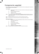
Before installing the dome, please remove the components from the packaging and verify that all items listed below have been supplied: 2060 Components supplied Indoor Dome 1x Note: Dedicated Micros 2060 Indoor Dome enclosure and camera (with incorporated safety bond) 1x 5mm A/F hexagonal socket key 1x Installation manual 1x Operation and Programming Manual The PSU must be 24VAC Power Supply with floating output and a minimum current of 1 amps.
2060 Mounting Configurations - External With appropriate brackets this dome enclosure can be mounted in any of the orientations shown below. The mounting bracket is prewired for ease of installation. Note: Mounting brackets may have been ordered and delivered separately. 1 2 4 3 7 5 6 9 8 1. 2. Wall/Pendant Mount (order code DM/90002) giving pendant or wall mount options. Pendant Mount bracket (order code DM/90003) giving pendant or wall mount options. 3.
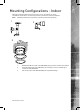
With appropriate brackets this dome enclosure can be mounted in any of the orientations shown below. The mounting bracket is prewired for ease of installation. Note: 2060 Mounting Configurations - Indoor Mounting brackets may have been ordered and delivered separately. 1 2 3 1. 2. 3. Wall/Pendant Mount (order code DM/90002) giving pendant or wall mount options. Corner Bracket (order code DM/90007) for mounting to corners of buildings in conjunction with DM/90002.
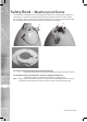
2060 Safety Bond - Weatherproof Dome The safety bond is designed to prevent damage to the dome if it is dropped during installation or maintenance. It should be connected between the mounting point on the dome and a suitable secure position, either on the bracket or within the ceiling void. This point should be selected with the consideration that it will receive the full force of the dome if it is dropped. A B For wall, pendant & snowdrop/parapet mounted domes; 1.
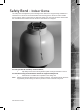
The safety bond is designed to prevent damage to the dome if it is dropped during installation or maintenance. It should be connected between the mounting point on the dome and a suitable secure position, either on the bracket or within the ceiling void. This point should be selected with the consideration that it will receive the full force of the dome if it is dropped. 2060 Safety Bond - Indoor Dome For wall, pendant & snowdrop mounted domes; 1.
2060 Ceiling Mounting - Weatherproof dome 1. Note: Cut or drill a hole in the ceiling in the required position using the pattern shown below. The installer is responsible for ensuring the fixings used to mount the dome are suitable for the material and will adequately support the weight of the dome. Ø15mm 1 slot 160mm m 113mm 2.
Note: Attach the Transfer Disc to the top of the dome enclosure using 4x prefitted M6 cap head screws (D). Fit the safety bond bracket (E) as shown. 2060 3. 4. 5. Note: Fit the safety bond between the enclosure and the mounting disk. Offer the dome enclosure up to the ceiling mounting disk, (shown upper right) engaging the screw heads (C) into the keyhole slots on the base of the dome (F) enclosure.
2060 Wall Mounting Bracket 1. Note: Remove the bracket base by unscrewing the outer trilobular fixings, then mark and drill 4x Ø7mm holes using the bracket base casting as a pattern. Use a spirit bubble level against one of the flats to align accurately. 2. If mounting onto masonry, insert 4x M6 rawlplugs into the wall until flush. 3. Offer the bracket base casting into position and fasten to the wall using appropriate fixings.
Note: 2060 Tile Mounting - Weatherproof Dome 1. Cut or drill a hole in the tile in the required position using the pattern shown below. The installer is responsible for ensuring the fixings used to mount the dome are suitable for the material and will adequately support the weight of the dome. m 5m 1 Ø2 4xØ7mm 255mm 255mm 113mm 2. Attach the mounting disc (A) to the dome in the chosen position and use 3 of the existing M4 dome hd screws to attach the hemisphere to the dome.
2060 Note: 14 3. Place dome, complete with attached mounting disc, into the pre-cut hole (B) in the tile from beneath. 4. 5. 6. From above, clamp to the tile via 2 x off split clamp rings (C). Secure the mounting disc with 4 x supplied off M6 socket button head fixings (D). Fit the supplied safety bond (E) to an attachment point in the ceiling.
2060 Dome Mounting - Weatherproof Dome 1. Note: Secure & hang the dome to the bracket by attaching the safety bond spring clip into the eyelet (A) 2. Connect the central connector supplying power & control to the dome (B). Ensure power is OFF before connecting the dome. 3. 4. Lift the dome to the bracket flange ensuring head of screws pass through the keyhole slots. Twist to locate and lock. Tighten the 4 top mounting fixings with 5mm A/F Hexagonal key (as supplied) to secure.
2060 Dome Mounting - Indoor Dome 1. Note: Secure & hang the dome to the bracket by attaching the safety bond spring clip to eyelet (as shown). Wall bracket shown. Procedure is the same for Snowdrop/Roof Parapet installation. Note: 2. Connect the central connector supplying power & control to the dome. Ensure power is OFF before connecting the dome. 3. 4. 16 Lift the dome to bracket flange ensuring head of screws (previously fitted M6x20mm Caphead Screw) pass through the keyhole slots.
2060 Tile Mounting - Indoor Dome Ø190mm 3 x Ø6mm 204mm PCD A C D B E F 1. Note: Remove the selected tile that will have the dome mounted to it. Use the mounting ring (B) as a template to mark the drilling positions of the 3 x supporting holes on a 204mm pitch circle diameter (6mmØ holes, if using the supplied cavity plugs (A)) and the 190mmØ hole for the dome. Fit the cavity plugs (A) to the holes.
2060 Electrical Connections - Weatherproof Dome The Dedicated Micros 2060 external connections are via an IP66 Amphenol connector with 3 metre composite cable flying lead that can be extended to 30 metres max., comprising co-ax, power pair & RS485 pair. This lead should be connected to the boxed P.S.U. supplied with the dome. A B a. Multicore cable with integral Co-ax (Video) b. Co-ax.
The dome requires connection to the power supply and to the BNC connection of the DVR. Use the serial port connection if serial telemetry is required. There is no prepared cable included, the connector for the camera is included.
60 Control Configuration The DM 2060 Dome can be controlled by one of three methods. The configuration drawings show the three connection arrangements. DM 2060 domes are delivered with the address switches set at FD (DM/Dennard UTC). DM 2060 with rx domes are delivered with the address switches set at 01. RS485 The switches on each dome must be set to a unique RS485 camera address, refer to ‘Switch Configuration - Indoor and Weatherproof Domes ->RS485 Serial Connection’.
The dome switches must be set according to the UTC protocol, , refer to ‘Switch Configuration - Indoor and Weatherproof Domes’.
2060 Control Switches - Weatherproof Dome To access the address switches and the RS485 termination switch, remove the outer hemisphere as shown above. The location of the switches is also shown. This operation should be carried out in an office type environment to avoid ingress of moist air. Note: 22 When reassembling the dome, check the hemisphere sealing gasket is in place and that the hemisphere retaining screws are retightened to avoid water ingress.
2060 Control Switches - Indoor Dome To access the address switches and the RS485 termination switch, remove the outer hemisphere by popping off the external trim and removing and retaining the three screws fastening it onto the body. Remove and retain the four screws securing the shield to the head and lift off the shield. The location of the switches is also shown. This operation should be carried out in an clean, dry environment.
2060 Switch Configuration - Indoor and Weatherproof Domes The same address switches are used for both RS485 and up the coax control. Up the Coax Configuration Switch settings The switches are color coded, blue and yellow, and are located inside the dome camera housing. Configure the switches for the controller being used as shown in table below. Note: The switches are factory set to FD (DM up the coax control).
2060 The dome will display its switch setting when first powered on as the screen will show (in the example above) “CAM 05”. Set the individual RS485 address for the dome on the blue and yellow switches fitted inside the dome housing. Set each switch to its desired position as shown in the table. Extended RS485 addressing The dome can be configured to allow up to 239 Dennard or Pelco P RS485 addresses to be used. The mechanism needs to be removed from the dome to enable this. 1. 2. 3.
2060 Termination All Dedicated Micros 2060 domes are fitted with a termination switch, shown above. If a single dome is connected on the RS485 line, or if a star configuration is used, the termination switch should be switched to ‘IN’ (towards the colored address switches). If multiple domes are connected in a ‘daisy chain’ configuration, then only the last dome in the chain should be switched to ‘IN’. All other domes in the chain should be switched to “OUT’.
2060 Circuit diagram drx options 500mA FUSE L 240V AC E I/P N 240V 0V RD 24Vac 2A5 BK GN/YL BL 2Amp FUSE RD BR WH/RD WH/BK POWER FROM DOME BL 250mA FUSE WH/RD 9V 100mA WH/BK 9Vac 100mA TO drx100 CARD FITTED CALL SEQUENCES LINK J6/4-5 LOCAL ALARM HANDLING REMOVED CALL PRESET POSITIONS LINK J6/1-2 STARTS SEQUENCE 1 AFTER 10 MINS INACTIVITY J6 J4 9-12V SUPPLY or TWISTED PAIR 1/P RS485 FROM DOME GN YL ALARM O/P ALARM I/P’s 4 OFF J3 VIDEO IN FROM DOME U2 AC AC TP TP GND C1 C2 C3 C4 GND A
2060 Troubleshooting No Picture Cause 1. Check the Input and Output voltage 2. Check the continuity on the power and video cables. 3. Check the multicore cable on the weatherproof dome; Pin Signal 1 Video 2 Video screen 3 Data + (yellow) 4 Data - (green) 5 24V neutral (blue) 6 24V live (red) E Earth (drain wire) No Control 1. Check the DVR is set to use the correct telemetry protocol and address settings. 2.
2060 Note: 3. Select ‘NVM Services’. 4. Select ‘Reload Factory defaults’. This will delete all preset positions and tours from the dome memory. Software Version To check the version of software installed in the dome; 1. Open the Technician Menu (refer to the Operation and Programming manual for details on accessing the menus). 2. Select ‘Maintenance Services’. 3. Select ‘Software Version’. The OSD will display the version of software installed in the dome.
2060 Appendix A DM 2060 Fixed Attitude Dome Camera - Setup Telemetry cameras can be positioned remotely, fixed atitude cameras require manual adjustment to position the camera. Framing the desired camera image will be easier using a local monitor. To Frame the image from a Fixed attitude camera; 1. Unscrew the 6x fixings securing the outer hemisphere to the casing and remove. 2. Note: Grip the inner hemisphere and rotate to adjust the Pan position of the camera.
The Dedicated Micros 2060 Fixed Attitude Camera Dome is supplied with an IP66 Amphenol connector with 3 metre composite cable flying lead. The connector mates with the dome as shown in the image below. 2060 DM 2060 Fixed Attitude Dome Camera - Electrical Connections A B a. Multicore cable with integral Co-ax (Video) b. Co-ax. (Video) The co-ax and power wires are always connected, the RS 485 wires are only connected when an external protocol converter is fitted or an RS485 controller is being used.
2060 DM 2060 Fixed Attitude Dome Camera - ‘Zoom Cam’ Setup The DM 2060 Fixed Attitude ‘Zoom Cam‘ is equipped wih the ‘zoom cam’ high resolution camera. This offers a range of features which are described below. 1. Note: Control Remote zoom control requires a Dennard, BBV or DM telemetry controller and the removal of lnk ‘B’ (refer to ‘View of right side of camera’ below and to point 6). 2.
Dedicated Micros ©2009 2060 Notes 33
2060 34 Notes Dedicated Micros ©2009
Appendix A................................................................................................................................................... 30 Camera Version............................................................................................................................................ 29 Ceiling Mounting - Weatherproof dome........................................................................................................ 10 CE NOTICE (EUROPEAN UNION).......................
Dedicated Micros Ltd. 1200 Daresbury Park, Daresbury, Cheshire, WA4 4HS, UK Dedicated Micros USA. 14434 Albemarle Point Place, Suite 100, Chantilly, Virginia 20151 USA Dedicated Micros Benelux Joseph Chantraineplantsoen 1, 3070 Kortenberg, Belgium Dedicated Micros Europe Hamtorstraße 9, 41460 Neuss, Germany Dedicated Micros, Australia PTY.