USB-RS485-STICK Hardware-Description 2010 Oktober
INDEX 1. Introduction 4 1.1. General remarks 4 1.2. Customer satisfaction 4 1.3. Customer response 4 2. Hardware description 6 2.1. Technical data 7 2.2. Pin assignment connector 8 2.2.1. 9pol. D-SUB male 8 2.3. LED's 3. Software 3.1. "VCP driver (Virtual COM-Port)" installation 4. Appendix 9 11 11 14 4.1. Product information 14 4.2. Revisions 15 4.3.
Introduction I Introduction | Seite 3
1. Introduction 1.1. General remarks First of all, we would like to congratulate you to the purchase of a high quality DEDITEC product. Our products are being developed by our engineers according to quality requirements of high standard. Already during design and development we take care that our products have -besides quality- a long availability and an optimal flexibility. Modular design The modular design of our products reduces the time and the cost of development.
Hardware description II Hardware description | Seite 5
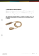
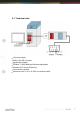
2. Hardware description With this handy stick your are able to connect your PC/Notebook to the world of RS-485 devices. The galvanical isolation electrically separates the PC from the RS-485 interface. Disruptive impulses from the RS-485 side, that destroy such converters, are now things of the past. With the help of galvanical isolation it is possible to connect your PC to industrial facilities that operate on an different electrical level than the used PC or notebook.
2.1. Technical data +5V power supply USB to RS-485 converter galvanically isolated 50 Baud ..
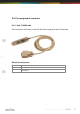
2.2. Pin assignment connector 2.2.1. 9pol. D-SUB male The connection to the stick on the RS-485 side is made by a 9pol. D-Sub male.
2.3. LED's Two LED signalize send and receive events.
Software III Software | Seite 10
3. Software 3.1. "VCP driver (Virtual COM-Port)" installation Insert the DEDITEC driver CD in your drive and start “vcp_driver_install.exe”. The “VCP driver (Virtual COM-Port)” software is also available at http://www. deditec.de/en/entwicklungstools/download.html. Press “Install”.
The driver will be installed. The “VCP Driver (Virtual COM-Port)” Software has been installed now. Press “Close” to finish installation.
Appendix IV Appendix | Seite 13
4. Appendix 4.1. Product information Ord.no.: USB-RS485-STICK Product: USB-RS-485-converter with galvanic isolation Productlink: http://www.deditec.de/en/entwicklungstools/prod/usb-rs485stick.
4.2. Revisions Rev 1.00 Rev 2.
4.3. Copyrights and trademarks Linux is registered trade-mark of Linus Torvalds. Windows CE is registered trade-mark of Microsoft Corporation. USB is registered trade-mark of USB Implementers Forum Inc. LabVIEW is registered trade-mark of National Instruments. Intel is registered trade-mark of Intel Corporation AMD is registered trade-mark of Advanced Micro Devices, Inc.
RO-USB-INTERFACE Hardware-Description 2010 Oktober
INDEX 1. Introduction 5 1.1. General remarks 5 1.2. Customer satisfaction 5 1.3. Customer response 5 2. Hardware description 7 2.1. Overview screen 7 2.2. Technical data 8 2.3. Plug-in connector of the module 9 2.3.1. Power supply 2.3.2. USB interface 2.4. Control LEDs 2.4.1. Definition of the LEDs 3. Software 9 9 10 10 12 3.1. Using our products 3.1.1. Access via graphical applications 3.1.2. Access via the DELIB driver library 3.1.3. Access via protocol 3.1.4.
INDEX 4. Appendix 24 4.1. Revisions 24 4.2.
Introduction I Introduction | Seite 4
1. Introduction 1.1. General remarks First of all, we would like to congratulate you to the purchase of a high quality DEDITEC product. Our products are being developed by our engineers according to quality requirements of high standard. Already during design and development we take care that our products have -besides quality- a long availability and an optimal flexibility. Modular design The modular design of our products reduces the time and the cost of development.
Hardware description II Hardware description | Seite 6
2. Hardware description 2.1. Overview screen The figure below shows the control module with USB-interface (left side) combined with an input/output module (right side). For a connection to the USB bus, an adequate adapter module in form of a USB-stick is included. The figure below shows the control module with USB interface (left side) combined with a flexible conntector input/output module (right side). For a connection to the USB bus, an adequate adapter module in form of a USB-stick is included with.
2.2. Technical data Single power supply +7V..+24V DC 7 control LEDs USB interface Transmission range up to 100m! USB 2.0 and USB 1.1 Data transfer speed: 12 MBit/s or 1,5 MBit/s Galvanically isolated interface using optocouplers 9 pol.
2.3. Plug-in connector of the module 2.3.1. Power supply The input-power-supply-range lies between +7V and +24V DC. Power supply can be realized with a standard AC/DC adaptor with 1A output current. A suitable plug-in connector is included. 2.3.2. USB interface module in form of a USB stick with a connection cable. The stick has two optocouplers ensuring a galvanical isolation to the PC. The other end of the adapater is a 9 pol. D-SUB connector which is connected to the RO-module.
2.4. Control LEDs The USB module has a series of control LEDs. They are used for easy visual indication of various state functions. While switching-on the module, it should signalize the following sequence: all five LEDs flashing briefly right LED (I/O access) flashing briefly all five LEDs flashing briefly 2.4.1.
Software III Software | Seite 11
3. Software 3.1. Using our products 3.1.1. Access via graphical applications We provide driverinterfaces e.g. for LabVIEW and ProfiLab. The DELIB driver library is the basis, which can be directly activated by ProfiLAB. For LabVIEW, we provide a simple driver connection with examples! 3.1.2. Access via the DELIB driver library In the appendix, you can find the complete function reference for the integration of our API-functions in your software.
3.1.4. Access via provided test programs We provide simple handling test programs for the most important functions of our products. These will be installed automatically by the installation of the DELIB driver library. So you can test directly e.g. relays or you can check the voltage of an A/D converter.
3.2. DELIB driver library 3.2.1. Overview The following figure explains the structure of the DELIB driver library The DELIB driver library allows an uniform response of DEDITEC hardware with particular consideration of the following viewpoints: Independent of operating system Independent of programming language Independent of the product Program under diverse operating systems The DELIB driver library allows an uniform response of our products on diverse operating systems.
Program with diverse programming languages We provide uniform commands to create own applications. This will be solved by the DELIB driver library. You choose the programming language! It can be simply developed applications under C++, C, Visual Basic, Delphi or LabVIEW®. Program independent of the interface Write your application independent of the interface ! Program an apllication for an USB product of us.
3.2.2. Supported operating systems Our products support the following operating systems: Windows 2000 Windows XP Windows Vista Windows 7 Linux 3.2.3. Supported programming languages Our products are responsive via the following programming languages: C C++ C# Delphi VisualBasic VB.
3.2.4. Installation DELIB driver library DELIB stands for DEDITEC Library and contains the necessary libraries for the modules in the programming languages C, Delphi and Visual Basic. Insert the DEDITEC driver CD into the drive and start „delib_install.exe“. The DELIB driver library is also available on http://www.deditec.en/delib Click on „Install“.
The drivers will be installed. The DELIB driver library is now installed. Press „Close“ to finish the installation. You can configure your module with the „DELIB Configuration Utility“ (see next chapter). This is only necessary, if more than one module is present.
3.2.5. DELIB Configuration Utility Start the “DELIB Configuration Utility” as follows: Start Programs DEDITEC DELIB DELIB Configuration Utility. The „DELIB Configuration Utility“ is a program to configure and subdivide identical USB-modules in the system. This is only necessary if more than one module is present.
3.3. Test programs 3.3.1. Digital Input-Output Demo Start “Digital Input-Output Demo” as follows: Start Programme DEDITEC DELIB Digital Input-Output Demo. The screenshot shows a test of the RO-USB-O64-R64. The configuration of the module (64 inputs and 64 outputs) is shown on the upper left side.
3.3.2. Analog Input-Output Demo Start “Analog Input-Output Demo” as follows: Start Programme DEDITEC DELIB Analog Input-Output Demo. The screenshot shows a test of the RO-USB-AD16-DA2_ISO. The configuration of the module (16 A/D inputs and 2 D/A outputs) is shown on the upper left side.
3.3.3. Stepper Demo Start “Stepper Demo” as follows: Start Programme DEDITEC DELIB Stepper Demo. The screenshot shows a test of the RO-USB-STEPPER2. The configuration of the module (2 Stepper) is shown on the upper left side.
Appendix IV Appendix | Seite 23
4. Appendix 4.1. Revisions Rev 1.00 Rev 2.
4.2. Copyrights and trademarks Linux is registered trade-mark of Linus Torvalds. Windows CE is registered trade-mark of Microsoft Corporation. USB is registered trade-mark of USB Implementers Forum Inc. LabVIEW is registered trade-mark of National Instruments. Intel is registered trade-mark of Intel Corporation AMD is registered trade-mark of Advanced Micro Devices, Inc.
RO-STEPPER2 Hardware Description 2010 November
INDEX 1. Introduction 6 1.1. General remarks 6 1.2. Customer satisfaction 6 1.3. Customer response 6 2. Hardware description 8 2.1. Overview screen 8 2.2. Technical data 9 2.3. Stepping motor control 9 2.4. Stepper connection wiring (10pol) - pinout 3. Software 10 12 3.1. Using our products 3.1.1. Access via graphical applications 3.1.2. Access via the DELIB driver library 3.1.3. Access via protocol 3.1.4. Access via provided test programs 3.2. DELIB driver library 3.2.1. Overview 3.2.
INDEX 4.2. Error handling 25 25 4.2.1. DapiGetLastError 4.2.2. DapiGetLastErrorText 26 4.3. Stepper motor functions 27 27 4.3.1. DapiStepperCommands 4.3.1.1. DAPI_STEPPER_CMD_GO_POSITION 27 4.3.1.2. DAPI_STEPPER_CMD_GO_POSITION_RELATIVE 28 4.3.1.3. DAPI_STEPPER_CMD_SET_POSITION 29 4.3.1.4. DAPI_STEPPER_CMD_SET_FREQUENCY 30 4.3.1.5. DAPI_STEPPER_CMD_GET_FREQUENCY 31 4.3.1.6. DAPI_STEPPER_CMD_SET_FREQUENCY_DIRECTLY 32 4.3.1.7. DAPI_STEPPER_CMD_STOP 33 4.3.1.8.
INDEX 4.4. Example program 5. Appendix 59 62 5.1. Revisions 62 5.2.
Introduction I Introduction | Seite 5
1. Introduction 1.1. General remarks First of all, we would like to congratulate you to the purchase of a high quality DEDITEC product. Our products are being developed by our engineers according to quality requirements of high standard. Already during design and development we take care that our products have -besides quality- a long availability and an optimal flexibility. Modular design The modular design of our products reduces the time and the cost of development.
Hardware description II Hardware description | Seite 7
2. Hardware description 2.1. Overview screen The lower figure shows a module with a terminal block and corresponding numbered connection ports. The following figure shows a flexible stepper module with a terminal block and corresponding numbered connection ports.
2.2. Technical data Common: Module for two stepper motors Comfortable connector system with ejection mechanism Can be combined without any problem to other modules of the RO series Configurable parameters Start-/ stop frequency Maximum stepping frequency Acceleration slope Deceleration slope Phase current Hold current Hold time 2.3. Stepping motor control Every parameter can be conveniently set using the DELIB library. Two reference switches are used to reach a reference position.
2.4. Stepper connection wiring (10pol) - pinout Pinout of a socket connector and also of a stepper motor: Pin 1 3 5 7 9 24 V supply) Phase 1 Phase 1 Phase 2 Phase 2 (motor (+) (-) (+) (-) Pin power 2 0 V (motor power supply) 4 6 8 10 Reference switch 2*) Reference switch 1*) End switch 2 *) End switch 1 *) *) The switches must be connected towards 24 V.
Software III Software | Seite 11
3. Software 3.1. Using our products 3.1.1. Access via graphical applications We provide driverinterfaces e.g. for LabVIEW and ProfiLab. The DELIB driver library is the basis, which can be directly activated by ProfiLAB. For LabVIEW, we provide a simple driver connection with examples! 3.1.2. Access via the DELIB driver library In the appendix, you can find the complete function reference for the integration of our API-functions in your software.
3.1.4. Access via provided test programs We provide simple handling test programs for the most important functions of our products. These will be installed automatically by the installation of the DELIB driver library. So you can test directly e.g. relays or you can check the voltage of an A/D converter.
3.2. DELIB driver library 3.2.1. Overview The following figure explains the structure of the DELIB driver library The DELIB driver library allows an uniform response of DEDITEC hardware with particular consideration of the following viewpoints: Independent of operating system Independent of programming language Independent of the product Program under diverse operating systems The DELIB driver library allows an uniform response of our products on diverse operating systems.
Program with diverse programming languages We provide uniform commands to create own applications. This will be solved by the DELIB driver library. You choose the programming language! It can be simply developed applications under C++, C, Visual Basic, Delphi or LabVIEW®. Program independent of the interface Write your application independent of the interface ! Program an apllication for an USB product of us.
3.2.2. Supported operating systems Our products support the following operating systems: Windows 2000 Windows XP Windows Vista Windows 7 Linux 3.2.3. Supported programming languages Our products are responsive via the following programming languages: C C++ C# Delphi VisualBasic VB.
3.2.4. Installation DELIB driver library DELIB stands for DEDITEC Library and contains the necessary libraries for the modules in the programming languages C, Delphi and Visual Basic. Insert the DEDITEC driver CD into the drive and start „delib_install.exe“. The DELIB driver library is also available on http://www.deditec.en/delib Click on „Install“.
The drivers will be installed. The DELIB driver library is now installed. Press „Close“ to finish the installation. You can configure your module with the „DELIB Configuration Utility“ (see next chapter). This is only necessary, if more than one module is present.
3.2.5. DELIB Configuration Utility Start the “DELIB Configuration Utility” as follows: Start Programs DEDITEC DELIB DELIB Configuration Utility. The „DELIB Configuration Utility“ is a program to configure and subdivide identical USB-modules in the system. This is only necessary if more than one module is present.
3.3. Test programs 3.3.1. Stepper Demo Start “Stepper Demo” as follows: Start Programme DEDITEC DELIB Stepper Demo.
The screenshot shows a test of the RO-USB-STEPPER2. The configuration of the module (2 Stepper) is shown on the upper left side.
DELIB API reference IV DELIB API reference | Seite 22
4. DELIB API reference 4.1. Management functions 4.1.1. DapiOpenModule Description This function opens a particular module. Definition ULONG DapiOpenModule(ULONG moduleID, ULONG nr); Parameters moduleID=Specifies the module, which is to be opened (see delib.h) nr=Indicates No of module which is to be opened. nr=0 -> 1. module nr=1 -> 2.
4.1.2. DapiCloseModule Description This command closes an opened module.
4.2. Error handling 4.2.1. DapiGetLastError Description This function returns the last registered error. Definition ULONG DapiGetLastError(); Parameters None Return value Error code 0=no error. (see delib.
4.2.2. DapiGetLastErrorText Description This function reads the text of the last registered error.
4.3. Stepper motor functions 4.3.1. DapiStepperCommands 4.3.1.1. DAPI_STEPPER_CMD_GO_POSITION Description With this command the motor will drive to a position. This command can only be used when the motor is not disabled and Go_Position or Go_Reference are not executed.
4.3.1.2. DAPI_STEPPER_CMD_GO_POSITION_RELATIVE Description With this command the motor will go to a relative position. In contrast to the command GO_POSITION, which goes to an absolute position, this command considers the current position. This command can only be used when the motor is not disabled and Go_Position or Go_Reference are not executed.
4.3.1.3. DAPI_STEPPER_CMD_SET_POSITION Description This command ist used to set the motor position. The resolution ist 1/16 Fullstep. This command may be used anytime.
4.3.1.4. DAPI_STEPPER_CMD_SET_FREQUENCY Description This command is used to set the motor reference frequency. The motor frequency regulation takes on the compliance of the acceleration and deceleration slope. Step losses do not occur. The motor reference frequency is related to the full-step-mode. The direction will be defined by the prefix. If the motor reference frequency is higher than the maximum frequency, the command is ignored.
4.3.1.5. DAPI_STEPPER_CMD_GET_FREQUENCY Description This command is used to read the motor frequency. This command can be used everytime.
4.3.1.6. DAPI_STEPPER_CMD_SET_FREQUENCY_DIRECTLY Description This command is used to set the motor frequency. The motor frequency regulation takes no funktion on the compliance of the acceleration and deceleration slope. The user is responsible. Step losses can occur. The motor reference frequency is related to the full-step. The direction can be defined by the prefix. The motor frequency can't exceed the maximum frequency.
4.3.1.7. DAPI_STEPPER_CMD_STOP Description This command is used to stop the motor, the deceleration slope will be used.
4.3.1.8. DAPI_STEPPER_CMD_FULLSTOP Description This command is used to stop the motors immediately without using the the deceleration slope. After this command the motor position might be ignorred because the motor has been stopped uncontrolled.
4.3.1.9. DAPI_STEPPER_CMD_DISABLE Description This command is used to disable/enable the motor. The motor stops or starts driving. This command can be only used when the motor stopped.
4.3.1.10. DAPI_STEPPER_CMD_SET_MOTORCHARACTERISTIC Description With this command, you can set motor characteristics.
Set Parameter-Accelerationslope par1=DAPI_STEPPER_MOTORCHAR_PAR_ACCELERATIONSLOPE par2=Acceleration slope [Full-step / 10ms] - (maximum value=1000) Set Parameter-Decelerationslope par1=DAPI_STEPPER_MOTORCHAR_PAR_DECELERATIONSLOPE par2=Deceleration slope [Full-step / 10ms] - (maximum value=1000) Set Parameter-Phasecurrent par1=DAPI_STEPPER_MOTORCHAR_PAR_PHASECURRENT par2=Phase current [mA] - (maximum value=1500) Set Parameter-Hold-Phasecurrent par1=DAPI_STEPPER_MOTORCHAR_PAR_HOLDPHASECURRENT par2=Phase curre
Set Parameter-Invert-END-Switch2 par1=DAPI_STEPPER_MOTORCHAR_PAR_INVERT_ENDSW2 par2=Endswitch2 is being inverted (0=normal / 1=inverted) Set Parameter-Invert-Ref-Switch1 par1=DAPI_STEPPER_MOTORCHAR_PAR_INVERT_REFSW1 par2=Referenzswitch1 is being inverted (0=normal / 1=inverted) Set Parameter-Invert-Ref-Switch2 par1=DAPI_STEPPER_MOTORCHAR_PAR_INVERT_REFSW2 par2=Referenzswitch2 is being inverted (0=normal / 1=inverted) Set Parameter-Invert-direction par1=DAPI_STEPPER_MOTORCHAR_PAR_INVERT_DIRECTION par2=invert
Set Parameter-GoReferenceFrequencyToOffSet par1=DAPI_STEPPER_MOTORCHAR_PAR_GOREFERENCEFREQUENCY_TO OFFSET par2=frequency [Full-step / s] - (maximum value=5000) Example program DapiStepperCommand(handle, motor, DAPI_STEPPER_CMD_SET_MOTORCHARACTERISTIC, DAPI_STEPPER_MOTORCHAR_PAR_STEPMODE, 4,0,0); // Schrittmode (Voll-, Halb-, Viertel-, Achtel-, Sechszehntelschritt) DapiStepperCommand(handle, motor, DAPI_STEPPER_CMD_SET_MOTORCHARACTERISTIC, DAPI_STEPPER_MOTORCHAR_PAR_GOFREQUENCY, 1000,0,0); // Schrittmode (Vo
DapiStepperCommand(handle, motor, DAPI_STEPPER_CMD_SET_MOTORCHARACTERISTIC, DAPI_STEPPER_MOTORCHAR_PAR_INVERT_ENDSW2, 0,0,0); // invertiere Funktion des Endschalter2 DapiStepperCommand(handle, motor, DAPI_STEPPER_CMD_SET_MOTORCHARACTERISTIC, DAPI_STEPPER_MOTORCHAR_PAR_INVERT_REFSW1, 0,0,0); // invertiere Funktion des Referenzschalterschalter1 DapiStepperCommand(handle, motor, DAPI_STEPPER_CMD_SET_MOTORCHARACTERISTIC, DAPI_STEPPER_MOTORCHAR_PAR_INVERT_REFSW2, 0,0,0); // invertiere Funktion des Referenzschalt
4.3.1.11. DAPI_STEPPER_CMD_GET_MOTORCHARACTERISTIC Description With this command, motor specific parameter can be read. This command may be used everytime. It is splitted in sub commands, that are analog to the parameters of the DAPI_STEPPER_CMD_SET_MOTORCHARATERISTIC.
Get Parameter-Hold-Phasecurrent par1=DAPI_STEPPER_MOTORCHAR_PAR_HOLDPHASECURRENT Get Parameter-Hold-Time par1=DAPI_STEPPER_MOTORCHAR_PAR_HOLDTIME Get Parameter-Status-LED-Mode par1=DAPI_STEPPER_MOTORCHAR_PAR_STATUSLEDMODE Get Parameter-Invert-END-Switch1 par1=DAPI_STEPPER_MOTORCHAR_PAR_INVERT_ENDSW1 Get Parameter-Invert-END-Switch2 par1=DAPI_STEPPER_MOTORCHAR_PAR_INVERT_ENDSW2 Get Parameter-Invert-Ref-Switch1 par1=DAPI_STEPPER_MOTORCHAR_PAR_INVERT_REFSW1 Get Parameter-Invert-Ref-Switch2 par1=DAPI_STEPPER_MO
Get Parameter-GoReferenceFrequencyAfterEndSwitch par1=DAPI_STEPPER_MOTORCHAR_PAR_GOREFERENCEFREQUENCY_AFT ERENDSWITCH Get Parameter-GoReferenceFrequencyToOffSet par1=DAPI_STEPPER_MOTORCHAR_PAR_GOREFERENCEFREQUENCY_TO OFFSET DELIB API reference | Seite 43
Return value Parameter-Stepmode par1=DAPI_STEPPER_MOTORCHAR_PAR_STEPMODE return=0 (Full-step) return=1 (1/2-step) return=2 (1/4-step) return=3 (1/8-step) return=4 (1/16-step) Parameter-GO-Frequency par1=DAPI_STEPPER_MOTORCHAR_PAR_GOFREQUENCY return=Speed [Full-step / s] - related to full-step Parameter-Start-Frequency par1=DAPI_STEPPER_MOTORCHAR_PAR_STARTFREQUENCY return=Startfrequency [Full-step / s] Parameter-Stop-Frequency par1=DAPI_STEPPER_MOTORCHAR_PAR_STOPFREQUENCY return=Stopfrequency [Full-step / s]
Parameter-Phasecurrent par1=DAPI_STEPPER_MOTORCHAR_PAR_PHASECURRENT return=Phase current [mA] Parameter-Hold-Phasecurrent par1=DAPI_STEPPER_MOTORCHAR_PAR_HOLDPHASECURRENT return=Phase current for motor hold [mA] Parameter-Hold-Time par1=DAPI_STEPPER_MOTORCHAR_PAR_HOLDTIME return=Time in that the hold goes to motorstop [ms] return=-1 / FFFF hex / 65535 dez (endless time) Parameter-Status-LED-Mode par1=DAPI_STEPPER_MOTORCHAR_PAR_STATUSLEDMODE return=Mode of the Status-LED return=0 (MOVE - LED is on if the ste
Parameter-Invert-Ref-Switch2 par1=DAPI_STEPPER_MOTORCHAR_PAR_INVERT_REFSW2 return=invert referenceswitch2 (0=normal / 1=inverted) Parameter-Invert-direction par1=DAPI_STEPPER_MOTORCHAR_PAR_INVERT_DIRECTION return=invert all direction details (0=normal / 1=inverted) Parameter-Endswitch-Stopmode par1= DAPI_STEPPER_MOTORCHAR_PAR_ENDSWITCH_STOPMODE return=setting of the stop behaviour (0=Fullstop / 1=Stop) Parameter-GoReferenceFrequnecyToEndSwitch par1=DAPI_STEPPER_MOTORCHAR_PAR_GOREFERENCEFREQUENCY_TOE NDSWITC
DAPI_STEPPER_MOTORCHAR_PAR_STARTFREQUENCY, 0, 0, 0); // Startfrequenz [Vollschritt / s] value = DapiStepperCommand(handle, motor, DAPI_STEPPER_CMD_GET_MOTORCHARACTERISTIC, DAPI_STEPPER_MOTORCHAR_PAR_STOPFREQUENCY, 0, 0, 0); // Stopfrequenz [Vollschritt / s] value = DapiStepperCommand(handle, motor, DAPI_STEPPER_CMD_GET_MOTORCHARACTERISTIC, DAPI_STEPPER_MOTORCHAR_PAR_MAXFREQUENCY, 0, 0, 0); // maximale Frequenz [Vollschritt / s] value = DapiStepperCommand(handle, motor, DAPI_STEPPER_CMD_GET_MOTORCHARACTERIST
// invertiere Funktion des Referenzschalterschalter1 value = DapiStepperCommand(handle, motor, DAPI_STEPPER_CMD_GET_MOTORCHARACTERISTIC, DAPI_STEPPER_MOTORCHAR_PAR_INVERT_REFSW2, 0, 0, 0); // invertiere Funktion des Referenzschalterschalter2 value = DapiStepperCommand(handle, motor, DAPI_STEPPER_CMD_GET_MOTORCHARACTERISTIC, DAPI_STEPPER_MOTORCHAR_PAR_INVERT_DIRECTION, 0, 0, 0); // invertiere alle Richtungsangaben value = DapiStepperCommand(handle, motor, DAPI_STEPPER_CMD_GET_MOTORCHARACTERISTIC, DAPI_STEPPE
4.3.1.12. DAPI_STEPPER_CMD_MOTORCHARACTERISTIC_EEPROM_SAVE Description The current motor characteristic will be stored in the EEPROM.
4.3.1.13. DAPI_STEPPER_CMD_MOTORCHARACTERISTIC_EEPROM_LOAD Description The motor characteristic can be loaded from the EEPROM.
4.3.1.14. DAPI_STEPPER_CMD_MOTORCHARACTERISTIC_LOAD_DEFAULT Description The characteristic of the motor is set back to default.
4.3.1.15. DAPI_STEPPER_CMD_GO_REFSWITCH Description The motor goes to the referece position.
4.3.1.16. DAPI_STEPPER_CMD_GET_CPU_TEMP Description The temperature of the CPU can be read.
4.3.1.17. DAPI_STEPPER_CMD_GET_MOTOR_SUPPLY_VOLTAGE Description The voltage supply of the CPU can be read.
4.3.2. DapiStepperGetStatus 4.3.2.1. DAPI_STEPPER_STATUS_GET_ACTIVITY Description With this command, some status informations (e.g. activity of the motor phase current) can be read. Definition ULONG DapiStepperGetStatus(handle, motor, DAPI_STEPPER_STATUS_GET_ACTIVITY); Parameters handle=This is the handle of an opened module motor=Number of addressed motor (1,2 ..
4.3.2.2. DAPI_STEPPER_STATUS_GET_POSITION Description With this command, the motor position can be read.
4.3.2.3. DAPI_STEPPER_STATUS_GET_SWITCH Description With this command, the status of the switches can be read.
4.3.3. DapiStepperCommandEx Description This extended command controls stepper motors. Definition ULONG DapiStepperCommandEx(ULONG handle, ULONG motor, ULONG cmd, ULONG par1, ULONG par2, ULONG par3, ULONG par4, ULONG par5, ULONG par6, ULONG par7); Parameters handle=This is the handle of an opened module motor=Number of addressed motor (1,2 ..) cmd=Extended command par1..7=Extended command-depedent parameter (see remarks) Remarks See delib.h for the extended commands and parameters.
4.4. Example program // **************************************************************************** // **************************************************************************** // **************************************************************************** // **************************************************************************** // **************************************************************************** // // (c) DEDITEC GmbH, 2009 // // web: http://www.deditec.de // // mail: vertrieb@deditec.
return; } // Zum Testen - ein Ping senden // ---------------------------------------------------printf("PING\n"); anz=10; for(i=0;i!=anz;++i) { data=DapiPing(handle, i); if(i==data) { // OK printf(".
Appendix V Appendix | Seite 61
5. Appendix 5.1. Revisions Rev 1.00 Rev 2.00 Rev 2.01 Rev 2.02 Rev 2.
5.2. Copyrights and trademarks Linux is registered trade-mark of Linus Torvalds. Windows CE is registered trade-mark of Microsoft Corporation. USB is registered trade-mark of USB Implementers Forum Inc. LabVIEW is registered trade-mark of National Instruments. Intel is registered trade-mark of Intel Corporation AMD is registered trade-mark of Advanced Micro Devices, Inc.
RO-Series Hardware-Description 2010 November
INDEX 1. Introduction 10 1.1. General remarks 10 1.2. Customer satisfaction 10 1.3. Customer response 10 2. Hardware description 12 2.1. Ethernet Interface 12 12 2.1.1. Hardware description 2.1.1.1. Overview screen 12 2.1.1.2. Technical data 14 2.1.1.3. Plug-in connector of the module 15 15 2.1.1.3.1. Power supply 2.1.1.3.2. Ethernet interface 2.1.1.4. Buttons of the module 15 2.1.1.5. Controll LEDs 17 16 17 2.1.1.5.1. Definition of LEDs 18 2.1.2. Restore basic configuration 2.1.2.
INDEX 32 2.2.2. Configuring the module 2.2.2.1. DIP-switches 32 2.2.2.2. The “special mode” 33 2.2.2.3. Software mode 34 2.2.2.4. DIP-switch mode 36 2.2.2.4.1. Setting up the transfer rate 36 2.2.2.4.2. Setting up the CAN module address 37 2.3. RS-232/RS-485 Interface 39 39 2.3.1. Hardware description 2.3.1.1. Overview screen 39 2.3.1.2. Technical data 40 2.3.1.3. Selecting between RS-232 or RS-485 interface 41 2.3.1.4. Plug-in connector of the module 43 2.3.1.4.1.
INDEX 2.5.1.1.1. Overview screen 55 2.5.1.1.2. Technical data 56 2.5.1.1.3. 16-bit counter 57 2.5.1.1.4. Registering short input pulses 57 57 2.5.1.1.5. Galvanically decouppled through optocouplers 2.5.1.1.6. Plug-in connector on the module 2.5.1.1.6.1Connection wiring 58 58 2.5.1.1.6.2Visual control of the inputs59 2.5.1.1.6.3Pinout 59 59 2.5.1.1.7. Variable input voltage range 2.5.1.1.7.1Changing the input voltage 60 61 2.5.1.2. Relay outputs 2.5.1.2.1. Overview screen 61 2.5.1.2.2.
INDEX 75 2.6.1.2.2. Technical data 76 2.6.1.2.3. Pinout 76 2.6.1.2.3.1A/D connection wiring (18pol) 77 2.6.1.3. RO-AD16_ISO 2.6.1.3.1. Overview screen 77 2.6.1.3.2. Technical data 78 79 2.6.1.3.3. Pinout 79 2.6.1.3.3.1A/D connection wiring (18pol) 80 2.6.1.4. RO-DA4 2.6.1.4.1. Overview screen 80 2.6.1.4.2. Technical data 81 2.6.1.4.3. Timeout-protection 82 82 2.6.1.4.4. Pinout 82 2.6.1.4.4.1D/A connection wiring (10pol) 83 2.6.1.5. RO-DA2_ISO 2.6.1.5.1. Overview screen 83 2.6.1.5.2.
INDEX 3.2.4. Installation DELIB driver library 3.2.5. DELIB Configuration Utility 3.3. Test programs 3.3.1. Digital Input-Output Demo 3.3.2. Analog Input-Output Demo 3.3.3. Stepper Demo 4. DELIB API reference 4.1. Management functions 4.1.1. DapiOpenModule 4.1.2. DapiCloseModule 4.2. Error handling 4.2.1. DapiGetLastError 4.2.2. DapiGetLastErrorText 4.3. Reading Digital inputs 4.3.1. DapiDIGet1 4.3.2. DapiDIGet8 4.3.3. DapiDIGet16 4.3.4. DapiDIGet32 4.3.5. DapiDIGet64 4.3.6. DapiDIGetFF32 4.3.7.
INDEX 125 4.5.4. DapiADGetVolt 4.5.5. DapiADGetmA 126 4.6. D/A outputs management 127 127 4.6.1. DapiDASetMode 4.6.2. DapiDAGetMode 4.6.3. DapiDASet 4.6.4. DapiDASetVolt 4.6.5. DapiDASetmA 4.6.6. DapiSpecialCmd_DA 129 130 131 132 133 4.7. Stepper motor functions 135 135 4.7.1. DapiStepperCommands 4.7.1.1. DAPI_STEPPER_CMD_GO_POSITION 135 4.7.1.2. DAPI_STEPPER_CMD_GO_POSITION_RELATIVE 136 4.7.1.3. DAPI_STEPPER_CMD_SET_POSITION 137 4.7.1.4. DAPI_STEPPER_CMD_SET_FREQUENCY 138 4.7.1.5.
INDEX 163 4.7.2. DapiStepperGetStatus 4.7.2.1. DAPI_STEPPER_STATUS_GET_ACTIVITY 163 4.7.2.2. DAPI_STEPPER_STATUS_GET_POSITION 164 4.7.2.3. DAPI_STEPPER_STATUS_GET_SWITCH 165 4.7.3. DapiStepperCommandEx 4.8. Output timeout management 4.8.1. DapiSpecialCMDTimeout 4.8.2. DapiSpecialCMDTimeoutGetStatus 4.9. Test functions 4.9.1. DapiPing 4.10. Example program 5. Appendix 166 167 167 168 169 169 170 173 5.1. Revisions 173 5.2.
Introduction I Introduction | Seite 9
1. Introduction 1.1. General remarks First of all, we would like to congratulate you to the purchase of a high quality DEDITEC product. Our products are being developed by our engineers according to quality requirements of high standard. Already during design and development we take care that our products have -besides quality- a long availability and an optimal flexibility. Modular design The modular design of our products reduces the time and the cost of development.
Hardware description II Hardware description | Seite 11
2. Hardware description 2.1. Ethernet Interface 2.1.1. Hardware description 2.1.1.1. Overview screen The figure shows the control module with ethernet interface (left side) combined with an input/output module (right side).
The figure shows the control module with ethernet interface (left side) combined with a flexible connector input/output module (right side).
2.1.1.2. Technical data Single power supply +7V..
2.1.1.3. Plug-in connector of the module 2.1.1.3.1. Power supply The input-power-supply-range lies between +7V and +24V DC.The power supply can be realized with a standard AC/DC adaptor with 1A output current. A suitable plug-in connector is delivered. 2.1.1.3.2. Ethernet interface The network connection is provided by a RJ45 socket.
2.1.1.4. Buttons of the module Left Button: Reset IP address to default (see chapter 5.1) Right Button: Reset firmware to factory settings. (see chapter 5.
2.1.1.5. Controll LEDs The Ethernet module has a series of control LEDs. They are used for easy visual indication of various state functions. While switching the module on, in normal operating mode, the module should signalize the following sequence: approx. 20 sec after switching the module on, LED 1 and 2 are flashing briefly. -> Operating system has been loaded successfully. Then LED 3 is on permanently and LED 1 is flashing. -> Module is ready. 2.1.1.5.1.
2.1.2. Restore basic configuration 2.1.2.1. Restore IP address The default value of the IP address is: 192.168.1.1 Left Button: Restore IP address to default (192.168.1.1): To restore the IP address proceed as follow: Push the button at least 5 sec. After that, the left LEDs "CPU Activity" and "Interface Activity" should be flashing four times (confirmation of receipt) After this, the module has following settings: IP address 192.168.1.1 Subnet mask 255.255.255.0 Standard gateway 192.168.1.254 2.1.2.2.
2.1.3. Firmware Update 2.1.3.1. DEDITEC Flasher Approach: Download the latest firmware inclusive software update. http://www.deditec. de/en/module/software/delib/download.html Extract all data to one folder Start the application deditec-flasher.exe 1. Select the interface. For ethernet press the key "E" 2. Select the module which you want to update. Press the key "M" for CPU interface 3.
2.1.3.2. Web interface Approach: 1.
1. Click on FW-Update 2. Select the file “ro_cpu_eth_fw.dfw” 3.
2.1.4. Configuring the module 2.1.4.1. Configuration via DELIB Configuration utility This method allows a simple configuration of the product. Following basic values can be changed. Module name IP address Net mask Default gateway DNS server Additionally with this tool all DEDITEC ethernet devices in the LAN network are displayed. The following pages describe how it works...
Start DELIB Configuration utility as follows: Start -> Programs -> DEDITEC -> DELIB -> DELIB Configuration Utility 1. Module Selection: select RO-ETH 2.
1. Scan RO-ETH modules: So you can find all DEDITEC ETH modules on local ethernet stream. Therefore we use an ethernet protocol which will not be routed. Because of that you can configure only modules which are connected to the bus. The advantage of this method is, that you can find modules which are not in the same sub net, of which you are configuring. 2. Click on the module, which you want to configure.
Here you can change the module name according to your wishes 1. You can change module name, IP address, net mask, default gateway and DNS server. 2. Write new Values to Module. Notice: At the configuration of the RO-ETH module should be paid attention to the IP address. It has to be in the same IP segment in which the control PC is. Of course you must not select an already used IP address.
2.1.4.2. Configuration via internal web server The RO-ETH module has an own web server by which it can be configured, too.
2.1.4.3. Factory settings The factory settings of the ethernet module include following settings: IP address: 192.168.1.1 The factory settings can be restored by pushing the left button -> see chapter 5.2 IP address 192.168.1.1 Subnet mask 255.255.255.0 Standard gateway 192.168.1.
2.2. CAN Interface 2.2.1. Hardware description 2.2.1.1. Overview screen The figure shows the control module with CAN-interface (left side) combined with an input/output module (right side). The figure shows the control module with CAN-interface (left side) combined with a flexible connector input/output module (right side).
2.2.1.2. Technical data Single power supply +7V..+24V DC 7 control LEDs CAN 2.0A (11 Bit addressing) CAN 2.0B (29 Bit addressing) Transmission range up to 10km (at 10Kbit/s) Easy to configure over DIP switches Galvanically isolated interface using optocouplers 9 pol.
2.2.1.3. Plug-in connector of the module 2.2.1.3.1. Power supply The input-power-supply-range lies between +7V and +24V DC. Power supply can be realized with a standard AC/DC adaptor with 1A output current. A suitable plug-in connector is included. 2.2.1.3.2. CAN interface The connection to the CAN bus is realized through a 9 pol D-SUB connector. It is galvanically isolated through optocouplers. The CAN module is configured over the PC’s RS-232 interface using the the included adaptor plug.
2.2.1.4. Control LEDs The CAN module has a series of control LEDs. They are used for easy visual indication of various state functions. While switching-on the module in DIP-switch mode oder software mode, the module should signalize the following sequence: all five LEDs flashing briefly right LED (I/O access) flashing briefly In ”special mode”, the following signal sequence should be seen: all five LEDs flashing briefly right LED (I/O access) flashing briefly all five LEDs flashing briefly 2.2.1.4.1.
2.2.2. Configuring the module In order to integrate a module into an existing bus system, it is necessary to first assign a free module address and the appropriate bit rate. The ”special mode” may be alternatively used to quickly operate the system. 2.2.2.1. DIP-switches Some of the settings are easily configurable using DIP-switches. Configurable are the ”special mode”, the activation of the extended IDs, the data transfer range or the module’s address.
2.2.2.2. The “special mode” The ”special mode” is to quickly and easily set the device to the default values. This is helpfull for a quick and easy setup and facilitates an error analysis or an initial operation. This mode is active, if switching the DIP-switches A7 and A8 to ”ON”. The remaining DIP-switches are disabled.
2.2.2.3. Software mode This module can configured in “software mode” only with the small CAN/SER program adpater, which is included in delivery. Configuration will be done by the serial interface of your pc. For using the software mode, the dip switches A7 and A8 must be set “on”. Dip switch changes will be taken over, only by restart of the module. Connect the module with a DSUB-9 cable to the RS-232 interface of your pc with the CAN/SER adapter and connect it with the CAN-module.
Approach: 1. Choose the RO-CAN module 2. Choose COM port, that is connected to the module 3. Test commuikation with RO-CAN module 4. This button shows the config of the module 5. Here you can save your configuration to the module 6.
2.2.2.4. DIP-switch mode In this mode, the module is entirely set up by DIP-switch. This mode is active, if DIP-switch A7=OFF and A8=OFF. The address range is 11 bit large (CAN 2.0A). The module-address is set using the DIP-switches (DIP A3..A1 und B8..B1). The Response-Modul-Addr = 1 (responses are sent to this address). 2.2.2.4.1. Setting up the transfer rate The bit rate is dependent on the CAN bus data transfer range. 3 DIP-switches are used to set the bit rate.
2.2.2.4.2. Setting up the CAN module address Any connected device to the CAN network needs a fix address in order to be directly accessed. With the 11 DIP-switches, up to 2047 different addresses are selectable. Further 18 addressing bits may be supplemented by software. To unlock this option, DIP-switch 7A must be set to ON.
Examples: Baud rate DIP-switch A3 DIP-switch A2 DIP-switch A1 DIP-switch B8 DIP-switch B7 DIP-switch B6 DIP-switch B5 DIP-switch B4 DIP-switch B3 DIP-switch B2 DIP-switch B1 Address 0 Off Off Off Off Off Off Off Off Off Off Off Address 117 Off Off Off Off On On On Off On Off On Address 588 Off On Off Off On Off Off On On Off Off Hardware description | Seite 38
2.3. RS-232/RS-485 Interface 2.3.1. Hardware description 2.3.1.1. Overview screen The figure shows the control module with RS-232/RS-485 interface (left side) combined with an input/output module (right side). The figure shows the control module with a RS-232/RS-485 interface (left side) combined with a flexible conntector input/output module (right side).
2.3.1.2. Technical data Single power supply +7V..+24V DC 7 control LEDs RS-232/RS-485 interface Easy to configure over DIP switches Galvanically isolated interface using optocouplers Connection through 9 pol.
2.3.1.3. Selecting between RS-232 or RS-485 interface The factory setting mode of the interface is RS-232. The following describes how to change the interface mode to RS-485. Notice! Bevore opening the device, please note the following: Disconnect the power supply (unplug AC/DC adaptor)! Do not touch electronic components. They could be destroyed by electrostatic discharge! If necessary, touch grounded metal casings or radiators. Remove a module‘s side element. Unscrew the three Phillips screws.
Header Interface Set jumper RS-232 Pin1 & Pin3 Pin2 & Pin4 Pin3 & Pin5 RS-485 Pin4 & Pin6 Pin7 & Pin8 Resistance terminator Pin9 & Pin10 Assembling the elements in done the reverse order.
2.3.1.4. Plug-in connector of the module 2.3.1.4.1. Power supply The input-power-supply-range lies between +7V and +24V DC. Power supply can be realized with a standard AC/DC adaptor with 1A output current. A suitable plug-in connector is included. 2.3.1.4.2. RS-232/RS-485 Interface The connection to the serial bus is realized through a 9 pol D-SUB conector. It is galvanically isolated through optocouplers.
2.3.1.4.2.1. RS-232 Pinout Pin 2 3 5 TX RX GND 2.3.1.4.2.2.
2.3.1.5. Control LEDs The RS-232/RS-485 module has a series of control LEDs. They are used for easy visual indication of various state functions. While switching the module on in normal operating mode, the module should signalize the following sequence: - all five LEDs flashing briefly - right LED (I/O access) flashing briefly In ”special mode”, the following signal sequence should be seen: - all five LEDs flashing briefly - right LED (I/O access) flashing briefly - all five LEDs flashing briefly 2.3.1.5.
2.3.2. Configuring the module In order to integrate a module into an existing bus system, it is necessary to first assign a free module address and the appropriate bit rate. The ”special mode” may be alternatively used to quickly operate the system. 2.3.2.1. DIP-switches Some of the settings are easily configurable using DIP-switches. Configurable are ”special mode”, the Baud rate, the module’s address or interface-specific settings.
2.3.2.2. The "special-mode" The ”special mode” is to quickly and easily set the device to the default values. This is helpfull for a quick and easy setup and facilitates an error analysis or an initial operation. This mode is active, if switching the DIP-switches A7 and A8 to ”ON. The remaining DIP-switches are disabled. The module is now set to a baud rate of 115Kbauds, the module number and ”echo” are inactive. 2.3.2.3.
2.3.2.4. Setting up Baud rate The table lists the possible Baud rates. The trasfer rate is set using the 4 DIPswitches (A1 to A4).
2.3.2.5. Setting up module address (RS-485 only) The operation in RS-485 mode allows to connect several modules to the bus. It is therefore necessary to assign an individual address to each module. This is realized by means of DIP-switches B1 to B8, resulting in a range of 0 to 255. The module-no. 0 is ignored, i.e. any no. will address the module.
2.4. USB Interface 2.4.1. Hardware description 2.4.1.1. Overview screen The figure below shows the control module with USB-interface (left side) combined with an input/output module (right side). For a connection to the USB bus, an adequate adapter module in form of a USB-stick is included. The figure below shows the control module with USB interface (left side) combined with a flexible conntector input/output module (right side).
2.4.1.2. Technical data Single power supply +7V..+24V DC 7 control LEDs USB interface Transmission range up to 100m! USB 2.0 and USB 1.1 Data transfer speed: 12 MBit/s or 1,5 MBit/s Galvanically isolated interface using optocouplers 9 pol.
2.4.1.3. Plug-in connector of the module 2.4.1.3.1. Power supply The input-power-supply-range lies between +7V and +24V DC. Power supply can be realized with a standard AC/DC adaptor with 1A output current. A suitable plug-in connector is included. 2.4.1.3.2. USB interface module in form of a USB stick with a connection cable. The stick has two optocouplers ensuring a galvanical isolation to the PC. The other end of the adapater is a 9 pol. D-SUB connector which is connected to the RO-module.
2.4.1.4. Control LEDs The USB module has a series of control LEDs. They are used for easy visual indication of various state functions. While switching-on the module, it should signalize the following sequence: all five LEDs flashing briefly right LED (I/O access) flashing briefly all five LEDs flashing briefly 2.4.1.4.1.
2.5. Digital in-/output modules 2.5.1. Hardware description Using the in-/output modules is based on two 16 pol. connectors with each 8 different current circuits. Each state of these (total 16) current circuits is signalized by a LED. The modules are numbered from left to right (see overview screen).
2.5.1.1. Opto-coupler inputs 2.5.1.1.1. Overview screen The figure shows two modules next to each other with corresponding numbering of the terminal blocks. The lower figure shows a flexible conntector module with 32 outputs and corresponding numbered ports. Each outer end of the module has a 26 pol. wire trap connector. Thus, multiple modules can be connected in series using a ribbon cable for each connection.
2.5.1.1.2. Technical data Variable power supply min. 5V, max.
2.5.1.1.3. 16-bit counter The first 16 input channels have each a 16 bit counter. Thus, events as light barriers, turnstiles or push-buttons are counted. Easy logical circuits are realizable, which may e.g. switch one or several outputs, if a counter reached a certain amount (set-point is reached). Please refer to the manual ”RO-series” to implement such logical circuits into software. 2.5.1.1.4.
2.5.1.1.6. Plug-in connector on the module As terminal block, user-friendly terminal strips with locking protection and ejection mechanism are used. They are reverse-polarity protected and allow quick replugging. The wire connection itself is realised with a screwless connector system. A tool is included with each module. 2.5.1.1.6.1. Connection wiring Connecting the wires is to be effected at the ports with the same numbering, for example: 1a & 1b, 2a & 2b. ...
2.5.1.1.6.2. Visual control of the inputs The state of each input is directly signalized by a separate LED. This simplifies to detect and rectify wiring errors, because the signals on the cables are directly observable. 2.5.1.1.6.3. Pinout Port 1 2 3 4 5 6 7 8 Pin 1a & 1b 2a & 2b 3a & 3b 4a & 4b 5a & 5b 6a & 6b 7a & 7b 8a & 8b Port 9 10 11 12 13 14 15 16 Pin 9a & 9b 10a & 10b 11a & 11b 12a & 12b 13a & 13b 14a & 14b 15a & 15b 16a & 16b 2.5.1.1.7.
2.5.1.1.7.1. Changing the input voltage Each terminal block has 8 inputs sudivided in two groups and each group has its own input voltage range (resulting groups: 1-4, 5-8, 9-12 und 13-16). Each group‘s input voltage range is defined by a corresponding resistor network. The following steps describes how to exchange one or more resistor networks. Notice! Bevore opening the device, please note the following: Disconnect the power supply (unplug AC/DC adaptor)! Do not touch electronic components.
2.5.1.2. Relay outputs 2.5.1.2.1. Overview screen The figure shows two modules next to each other with corresponding numbering of the terminal blocks. The lower figure shows a flexible conntector module with 32 outputs and corresponding numbered ports. Each outer end of the module has a 26 pol. wire trap connector. Thus, multiple modules can be connected in series using a ribbon cable for each connection.
2.5.1.2.2. Technical data Timeout-protection LED status indication of the outputs Galvanically isolated using optocouplers Comfortable connector system with ejection mechanism Expandable in 16 gradations Can be combined without any problem to other modules of the RO series Max. switching voltage: 36V Max. switching current: 1A Max. switching power: 20W Switching cycles according to the manufacturer: 10 Mio.
2.5.1.2.3. Timeout-protection The timeout-protection gives the possibility to switch-off automatically the outputs on its own to prevent damage. This takes place, if in a predefined time frame no communication with the module was possible. Reasons could be cable disruption, PC-crash and more. This way damage control, surcharge of connected equipment and risk of accidents can be avoided. Switching off the outputs is indicated by a LED. 2.5.1.2.4.
2.5.1.2.4.2. Connection wiring Connecting the wires is to be effected at the ports with the same numbering, for example: 1a & 1b, 2a & 2b. ... It is not necessary to take care to the correct polarity. 2.5.1.2.4.3. Visual control of the outputs The state of each output is directly signalized by a separate LED. This simplifies to detect and rectify wiring errors, because the signals on the cables are directly observable. 2.5.1.2.4.4.
2.5.1.3. MOSFET outputs 2.5.1.3.1. Overview screen The figure shows two modules next to each other with corresponding numbering of the terminal blocks. The lower figure shows a flexible conntector module with 32 outputs and corresponding numbered ports. Each outer end of the module has a 26 pol. wire trap connector. Thus, multiple modules can be connected in series using a ribbon cable for each connection.
2.5.1.3.2. Technical data Timeout-protection LED status indication of the outputs Galvanically isolated using optocouplers Comfortable connector system with ejection mechanism Expandable in 16 gradations Can be combined without any problem to other modules of the RO series Max. switching voltage: 30V DC Max. switching current: 2A DC Max.
2.5.1.3.3. Timeout-protection The timeout-protection gives the possibility to switch-off automatically the outputs on its own to prevent damage. This takes place, if in a predefined time frame no communication with the module was possible. Reasons could be cable disruption, PC-crash and more. This way damage control, surcharge of connected equipment and risk of accidents can be avoided. Switching off the outputs is indicated by a LED. 2.5.1.3.4.
2.5.1.3.4.2. Connection wiring Connecting the wires is to be effected at the ports with the same numbering, for example: 1a & 1b, 2a & 2b, ... Pay attention to the optocoupler’s output polarity while wiring, else the outputs will get damaged. Connect the positive voltage to port ”a”, and the switched positive voltage to port ”b”. 2.5.1.3.4.3.
2.6. Analog in-/output modules 2.6.1. Hardware description 2.6.1.1. RO-AD16-DA4 This module has 16 A/D channels and provides a good basis to convert voltages to digital values. It has furthermore 4 D/A outputs allowing to convert digital values to an analog voltage.
2.6.1.1.1. Overview screen The lower figure shows a module with two terminal blocks and corresponding numbered connection ports. The following figure shows a flexible conntector module with two terminal blocks and corresponding numbered connection ports.
2.6.1.1.2.
2.6.1.1.3. Timeout-protection The timeout-protection gives the possibility to switch automatically off the outputs on its own to prevent damage. This takes place, if in a predefined time frame no communication with the module was possible. Reasons could be cable disruption, PC-crash and more. This way damage control, surcharge of connected equipment and risk of accidents can be avoided. Switching off the outputs is indicated by a LED.
2.6.1.1.4. Pinout 2.6.1.1.4.1. A/D connection wiring (18pol) Pin 1 3 5 7 9 11 13 15 17 AGND AD1 AD3 AD5 AD7 AD9 AD11 AD13 Pin 2 4 6 8 10 12 14 16 AGND AD0 AD2 AD4 AD6 AD8 AD10 AD12 AD15 18 AD14 Pin 2 4 6 8 10 DA0 DA1 DA2 DA3 AGND 2.6.1.1.4.2.
2.6.1.2. RO-AD16 This module has 16 A/D input channels and provides a good basis to convert voltages to digital values. 2.6.1.2.1. Overview screen The lower figure shows a module with a terminal block and corresponding numbered connection ports. The following figure shows a flexible conntector module with a terminal block and corresponding numbered connection ports.
2.6.1.2.2.
2.6.1.2.3. Pinout 2.6.1.2.3.1.
2.6.1.3. RO-AD16_ISO This module has 16 A/D input channels (galvancally isolated) and provides a good basis to convert voltages to digital values. 2.6.1.3.1. Overview screen The lower figure shows a module with a terminal block and corresponding numbered connection ports. The following figure shows a flexible conntector module with a terminal block and corresponding numbered connection ports.
2.6.1.3.2.
2.6.1.3.3. Pinout 2.6.1.3.3.1.
2.6.1.4. RO-DA4 This module has 4 D/A outputs and provides a good basis to convert digital values to a voltage. 2.6.1.4.1. Overview screen The lower figure shows a module with a terminal block and corresponding numbered connection ports. The following figure shows a flexible conntector module with a terminal block and corresponding numbered connection ports.
2.6.1.4.2.
2.6.1.4.3. Timeout-protection The timeout-protection gives the possibility to switch automatically off the outputs on its own to prevent damage. This takes place, if in a predefined time frame no communication with the module was possible. Reasons could be cable disruption, PC-crash and more. This way damage control, surcharge of connected equipment and risk of accidents can be avoided. Switching off the outputs is indicated by a LED. 2.6.1.4.4. Pinout 2.6.1.4.4.1.
2.6.1.5. RO-DA2_ISO This module has 2 galvanically decoupled D/A outputs and provides a good basis to convert digital values to a voltage. 2.6.1.5.1. Overview screen The lower figure shows a module with a terminal block and corresponding numbered connection ports. The following figure shows a flexible conntector module with a terminal block and corresponding numbered connection ports.
2.6.1.5.2.
2.6.1.5.3. Timeout-protection The timeout-protection gives the possibility to switch automatically off the outputs on its own to prevent damage. This takes place, if in a predefined time frame no communication with the module was possible. Reasons could be cable disruption, PC-crash and more. This way damage control, surcharge of connected equipment and risk of accidents can be avoided. Switching off the outputs is indicated by a LED.
2.6.1.5.4. Pinout 2.6.1.5.4.1.
2.7. Stepper module 2.7.1. Hardware description 2.7.1.1. Overview screen The lower figure shows a module with a terminal block and corresponding numbered connection ports. The following figure shows a flexible stepper module with a terminal block and corresponding numbered connection ports.
2.7.1.2. Technical data Common: Module for two stepper motors Comfortable connector system with ejection mechanism Can be combined without any problem to other modules of the RO series Configurable parameters Start-/ stop frequency Maximum stepping frequency Acceleration slope Deceleration slope Phase current Hold current Hold time 2.7.1.3. Stepping motor control Every parameter can be conveniently set using the DELIB library. Two reference switches are used to reach a reference position.
2.7.1.4. Stepper connection wiring (10pol) - pinout Pinout of a socket connector and also of a stepper motor: Pin 1 3 5 7 9 24 V supply) Phase 1 Phase 1 Phase 2 Phase 2 (motor (+) (-) (+) (-) Pin power 2 0 V (motor power supply) 4 6 8 10 Reference switch 2*) Reference switch 1*) End switch 2 *) End switch 1 *) *) The switches must be connected towards 24 V.
Software III Software | Seite 90
3. Software 3.1. Using our products 3.1.1. Access via graphical applications We provide driverinterfaces e.g. for LabVIEW and ProfiLab. The DELIB driver library is the basis, which can be directly activated by ProfiLAB. For LabVIEW, we provide a simple driver connection with examples! 3.1.2. Access via the DELIB driver library In the appendix, you can find the complete function reference for the integration of our API-functions in your software.
3.1.4. Access via provided test programs We provide simple handling test programs for the most important functions of our products. These will be installed automatically by the installation of the DELIB driver library. So you can test directly e.g. relays or you can check the voltage of an A/D converter.
3.2. DELIB driver library 3.2.1. Overview The following figure explains the structure of the DELIB driver library The DELIB driver library allows an uniform response of DEDITEC hardware with particular consideration of the following viewpoints: Independent of operating system Independent of programming language Independent of the product Program under diverse operating systems The DELIB driver library allows an uniform response of our products on diverse operating systems.
Program with diverse programming languages We provide uniform commands to create own applications. This will be solved by the DELIB driver library. You choose the programming language! It can be simply developed applications under C++, C, Visual Basic, Delphi or LabVIEW®. Program independent of the interface Write your application independent of the interface ! Program an apllication for an USB product of us.
3.2.2. Supported operating systems Our products support the following operating systems: Windows 2000 Windows XP Windows Vista Windows 7 Linux 3.2.3. Supported programming languages Our products are responsive via the following programming languages: C C++ C# Delphi VisualBasic VB.
3.2.4. Installation DELIB driver library DELIB stands for DEDITEC Library and contains the necessary libraries for the modules in the programming languages C, Delphi and Visual Basic. Insert the DEDITEC driver CD into the drive and start „delib_install.exe“. The DELIB driver library is also available on http://www.deditec.en/delib Click on „Install“.
The drivers will be installed. The DELIB driver library is now installed. Press „Close“ to finish the installation. You can configure your module with the „DELIB Configuration Utility“ (see next chapter). This is only necessary, if more than one module is present.
3.2.5. DELIB Configuration Utility Start the “DELIB Configuration Utility” as follows: Start Programs DEDITEC DELIB DELIB Configuration Utility. The „DELIB Configuration Utility“ is a program to configure and subdivide identical USB-modules in the system. This is only necessary if more than one module is present.
3.3. Test programs 3.3.1. Digital Input-Output Demo Start “Digital Input-Output Demo” as follows: Start Programme DEDITEC DELIB Digital Input-Output Demo. The screenshot shows a test of the RO-USB-O64-R64. The configuration of the module (64 inputs and 64 outputs) is shown on the upper left side.
3.3.2. Analog Input-Output Demo Start “Analog Input-Output Demo” as follows: Start Programme DEDITEC DELIB Analog Input-Output Demo. The screenshot shows a test of the RO-USB-AD16-DA2_ISO. The configuration of the module (16 A/D inputs and 2 D/A outputs) is shown on the upper left side.
3.3.3. Stepper Demo Start “Stepper Demo” as follows: Start Programme DEDITEC DELIB Stepper Demo. The screenshot shows a test of the RO-USB-STEPPER2. The configuration of the module (2 Stepper) is shown on the upper left side.
DELIB API reference IV DELIB API reference | Seite 102
4. DELIB API reference 4.1. Management functions 4.1.1. DapiOpenModule Description This function opens a particular module. Definition ULONG DapiOpenModule(ULONG moduleID, ULONG nr); Parameters moduleID=Specifies the module, which is to be opened (see delib.h) nr=Indicates No of module which is to be opened. nr=0 -> 1. module nr=1 -> 2.
4.1.2. DapiCloseModule Description This command closes an opened module.
4.2. Error handling 4.2.1. DapiGetLastError Description This function returns the last registered error. Definition ULONG DapiGetLastError(); Parameters None Return value Error code 0=no error. (see delib.
4.2.2. DapiGetLastErrorText Description This function reads the text of the last registered error.
4.3. Reading Digital inputs 4.3.1. DapiDIGet1 Description This command reads a single digit input. Definition ULONG DapiDIGet1(ULONG handle, ULONG ch); Parameters handle=This is the handle of an opened module. ch=Specifies the number of input that is to be read (0 ..). Return value State of the input (0 / 1).
4.3.2. DapiDIGet8 Description This command reads 8 digital inputs simultaneously. Definition ULONG DapiDIGet8(ULONG handle, ULONG ch); Parameters handle=This is the handle of an opened module. ch=Specifies the number of the input, from which it begins to read from (0, 8, 16, 24, 32, ..) Return value State of the read inputs.
4.3.3. DapiDIGet16 Description This command reads 16 digital inputs simultaneously. Definition ULONG DapiDIGet16(ULONG handle, ULONG ch); Parameters handle=This is the handle of an opened module. ch=Specifies the number of the input, from which it begins to read from (0, 16, 32, ..) Return value State of the read inputs.
4.3.4. DapiDIGet32 Description This command reads 32 digital inputs simultaneously. Definition ULONG DapiDIGet32(ULONG handle, ULONG ch); Parameters handle=This is the handle of an opened module. ch=Specifies the number of the input, from which it begins to read from (0, 32, 64, ..) Return value State of the read inputs.
4.3.5. DapiDIGet64 Description This command reads 64 digital inputs simultaneously. Definition ULONGLONG DapiDIGet64(ULONG handle, ULONG ch); Parameters handle=This is the handle of an opened module. ch=Specifies the number of the input,from which it begins to read from (0, 64, ..) Return value State of the read inputs.
4.3.6. DapiDIGetFF32 Description This command reads the flip-flops from the inputs and resets them. (Input state change). Definition ULONG DapiDIGetFF32(ULONG handle, ULONG ch); Parameters handle=This is the handle of an opened module . ch=Specifies the number of the input, from which it begins to read from (0, 32, ..
4.3.7. DapiDIGetCounter Description This command reads the counter of a digital input Definition ULONG DapiDIGetCounter(handle, ch, par1); Parameters handle=This is the handle of an opened module. ch=Specifies the digital input, from which the counter will be read par1=0 (Normal counter function) par1=DAPI_CNT_MODE_READ_WITH_RESET (Reading and resetting counter) the Return value Value of the counter.
4.4. Setting Digital outputs 4.4.1. DapiDOSet1 Description This is the command to set a single output. Definition void DapiDOSet1(ULONG handle, ULONG ch, ULONG data); Parameters handle=This is the handle of an opened module ch=Specifies the number of the output to be set to (0 ..
4.4.2. DapiDOSet8 Description This command sets 8 digital outputs simultaneously. Definition void DapiDOSet8(ULONG handle, ULONG ch, ULONG data); Parameters handle=This is the handle of an opened module ch=Specifies the number of the output, from which it begins to write to (0, 8, 16, 24, 32, ..
4.4.3. DapiDOSet16 Description This command sets 16 digital outputs simultaneously. Definition void DapiDOSet16(ULONG handle, ULONG ch, ULONG data); Parameters handle=This is the handle of an opened module ch=Specifies the number of the output, from which it begins to write to (0, 16, 32, ..
4.4.4. DapiDOSet32 Description This command sets 32 digital outputs simultaneously. Definition void DapiDOSet32(ULONG handle, ULONG ch, ULONG data); Parameters handle=This is the handle of an opened module ch=Specifies the number of the output, from which it begins to write to (0, 32, 64, ..
4.4.5. DapiDOSet64 Description This command is to set 64 digital outputs. Definition void DapiDOSet64(ULONG handle, ULONG ch, ULONG data); Parameters handle=This is the handle of an opened module ch=Specifies the number of the output, from which it begins to write to (0, 64, ..
4.4.6. DapiDOReadback32 Description This command reads back the 32 digital outputs. Definition ULONG DapiDOReadback32(ULONG handle, ULONG ch); Parameters handle=This is the handle of an opened module ch=Specifies the number of the input, from which it begins to read from (0, 32, ..) Return value Status of 32 outputs.
4.4.7. DapiDOReadback64 Description This command reads back the 64 digital outputs. Definition ULONGLONG DapiDOReadback64(ULONG handle, ULONG ch); Parameters handle=This is the handle of an opened module ch=Specifies the number of the input, from which it begins to read from (0, 64, ..) Return value Status of 64 outputs.
4.5. A/D converter functions 4.5.1. DapiADSetMode Description This is the command to configure the input range of an A/D converter. Definition void DapiADSetMode(ULONG handle, ULONG ch, ULONG mode); Parameters handle=This is the handle of an opened module ch=Specifies the channel of the A/D converter (0 ..
Currents: ADDA_MODE_0_20mA ADDA_MODE_4_20mA ADDA_MODE_0_24mA ADDA_MODE_0_25mA ADDA_MODE_0_50mA DELIB API reference | Seite 122
4.5.2. DapiADGetMode Description This command reads the set mode of an A/D converter. For mode description see DapiADSetMode. Definition ULONG DapiADGetMode(ULONG handle, ULONG ch); Parameters handle=This is the handle of an opened module ch=Specifies the channel of the A/D converter (0 ..
4.5.3. DapiADGet Description This command reads a data value of one channel of an A/D converter Definition ULONG DapiADGet(ULONG handle, ULONG ch); Parameters handle=This is the handle of an opened module ch=Specifies the channel of the A/D converter (0 ..
4.5.4. DapiADGetVolt Description This command reads a data value of one channel of an A/D converter in volts. Definition float DapiADGetVolt(ULONG handle, ULONG ch); Parameters handle=This is the handle of an opened module ch=Specifies the channel of the A/D converter (0 ..
4.5.5. DapiADGetmA Description This command reads a data value of one channel of an A/D converter in mA. Definition float DapiADGetmA(ULONG handle, ULONG ch); Parameters handle=This is the handle of an opened module ch=Specifies the channel of the A/D converter (0 ..) Return value Value from the A/D converter in mA. Remarks This command is module dependent. It only works if the module also supports the current mode.
4.6. D/A outputs management 4.6.1. DapiDASetMode Description This command sets the mode for a D/A converter. Definition void DapiDASetMode(ULONG handle, ULONG ch, ULONG mode); Parameters handle=This is the handle of an opened module ch=Specifies the channel of the D/A converter (0 ..
Currents: ADDA_MODE_0_20mA ADDA_MODE_4_20mA ADDA_MODE_0_24mA ADDA_MODE_0_25mA ADDA_MODE_0_50mA DELIB API reference | Seite 128
4.6.2. DapiDAGetMode Description This command reads back the chosen mode of a D/A converter. Definition ULONG DapiDAGetMode(ULONG handle, ULONG ch); Parameters handle=This is the handle of an opened module ch=Specifies the channel of the D/A converter (0 ..
4.6.3. DapiDASet Description This command transfers a data value to a channel of a D/A converter. Definition void DapiDASet(ULONG handle, ULONG ch, ULONG data); Parameters handle=This is the handle of an opened module ch=Specifies the channel of the D/A converter (0 ..
4.6.4. DapiDASetVolt Description This command sets a voltage to a channel of a D/A converter. Definition void DapiDASetVolt(ULONG handle, ULONG ch, float data); Parameters handle=This is the handle of an opened module ch=Specifies the channel of the D/A converter (0 ..
4.6.5. DapiDASetmA Description This command sets a current to a channel of a D/A converter. Definition void DapiDASetmA(ULONG handle, ULONG ch, float data); Parameters handle=This is the handle of an opened module ch=Specifies the channel of the D/A converter (0 ..) data=Specifies the current, which is to be set [mA] Return value None Remarks This command depends on the module. It only works, if the module also supports the current mode.
4.6.6. DapiSpecialCmd_DA Description This command sets the voltage/current value to a D/A channel at powering up or after a timeout. (EEPROM Configuration) Definition void DapiSpecialCommand(handle, DAPI_SPECIAL_CMD_DA, cmd, ch, 0); Parameters handle=This is the handle of an opened module ch=Specifies the channel of the D/A converter (0, 1, 2, ..
Example program DapiSpecialCommand(handle, DAPI_SPECIAL_CMD_DA, DAPI_SPECIAL_DA_PAR_DA_LOAD_DEFAULT, 1, 0); //Zurücksetzen der EEPROMKonfiguration auf Default Konfiguration bei Kanal 1. DapiSpecialCommand(handle, DAPI_SPECIAL_CMD_DA, DAPI_SPECIAL_DA_PAR_DA_SAVE_EEPROM_CONFIG, 3, 0); Wandler Einstellungen in das EEPROM bei Kanal 3.
4.7. Stepper motor functions 4.7.1. DapiStepperCommands 4.7.1.1. DAPI_STEPPER_CMD_GO_POSITION Description With this command the motor will drive to a position. This command can only be used when the motor is not disabled and Go_Position or Go_Reference are not executed.
4.7.1.2. DAPI_STEPPER_CMD_GO_POSITION_RELATIVE Description With this command the motor will go to a relative position. In contrast to the command GO_POSITION, which goes to an absolute position, this command considers the current position. This command can only be used when the motor is not disabled and Go_Position or Go_Reference are not executed.
4.7.1.3. DAPI_STEPPER_CMD_SET_POSITION Description This command ist used to set the motor position. The resolution ist 1/16 Fullstep. This command may be used anytime.
4.7.1.4. DAPI_STEPPER_CMD_SET_FREQUENCY Description This command is used to set the motor reference frequency. The motor frequency regulation takes on the compliance of the acceleration and deceleration slope. Step losses do not occur. The motor reference frequency is related to the full-step-mode. The direction will be defined by the prefix. If the motor reference frequency is higher than the maximum frequency, the command is ignored.
4.7.1.5. DAPI_STEPPER_CMD_GET_FREQUENCY Description This command is used to read the motor frequency. This command can be used everytime.
4.7.1.6. DAPI_STEPPER_CMD_SET_FREQUENCY_DIRECTLY Description This command is used to set the motor frequency. The motor frequency regulation takes no funktion on the compliance of the acceleration and deceleration slope. The user is responsible. Step losses can occur. The motor reference frequency is related to the full-step. The direction can be defined by the prefix. The motor frequency can't exceed the maximum frequency.
4.7.1.7. DAPI_STEPPER_CMD_STOP Description This command is used to stop the motor, the deceleration slope will be used.
4.7.1.8. DAPI_STEPPER_CMD_FULLSTOP Description This command is used to stop the motors immediately without using the the deceleration slope. After this command the motor position might be ignorred because the motor has been stopped uncontrolled.
4.7.1.9. DAPI_STEPPER_CMD_DISABLE Description This command is used to disable/enable the motor. The motor stops or starts driving. This command can be only used when the motor stopped.
4.7.1.10. DAPI_STEPPER_CMD_SET_MOTORCHARACTERISTIC Description With this command, you can set motor characteristics.
Set Parameter-Accelerationslope par1=DAPI_STEPPER_MOTORCHAR_PAR_ACCELERATIONSLOPE par2=Acceleration slope [Full-step / 10ms] - (maximum value=1000) Set Parameter-Decelerationslope par1=DAPI_STEPPER_MOTORCHAR_PAR_DECELERATIONSLOPE par2=Deceleration slope [Full-step / 10ms] - (maximum value=1000) Set Parameter-Phasecurrent par1=DAPI_STEPPER_MOTORCHAR_PAR_PHASECURRENT par2=Phase current [mA] - (maximum value=1500) Set Parameter-Hold-Phasecurrent par1=DAPI_STEPPER_MOTORCHAR_PAR_HOLDPHASECURRENT par2=Phase curre
Set Parameter-Invert-END-Switch2 par1=DAPI_STEPPER_MOTORCHAR_PAR_INVERT_ENDSW2 par2=Endswitch2 is being inverted (0=normal / 1=inverted) Set Parameter-Invert-Ref-Switch1 par1=DAPI_STEPPER_MOTORCHAR_PAR_INVERT_REFSW1 par2=Referenzswitch1 is being inverted (0=normal / 1=inverted) Set Parameter-Invert-Ref-Switch2 par1=DAPI_STEPPER_MOTORCHAR_PAR_INVERT_REFSW2 par2=Referenzswitch2 is being inverted (0=normal / 1=inverted) Set Parameter-Invert-direction par1=DAPI_STEPPER_MOTORCHAR_PAR_INVERT_DIRECTION par2=invert
Set Parameter-GoReferenceFrequencyToOffSet par1=DAPI_STEPPER_MOTORCHAR_PAR_GOREFERENCEFREQUENCY_TO OFFSET par2=frequency [Full-step / s] - (maximum value=5000) Example program DapiStepperCommand(handle, motor, DAPI_STEPPER_CMD_SET_MOTORCHARACTERISTIC, DAPI_STEPPER_MOTORCHAR_PAR_STEPMODE, 4,0,0); // Schrittmode (Voll-, Halb-, Viertel-, Achtel-, Sechszehntelschritt) DapiStepperCommand(handle, motor, DAPI_STEPPER_CMD_SET_MOTORCHARACTERISTIC, DAPI_STEPPER_MOTORCHAR_PAR_GOFREQUENCY, 1000,0,0); // Schrittmode (Vo
DapiStepperCommand(handle, motor, DAPI_STEPPER_CMD_SET_MOTORCHARACTERISTIC, DAPI_STEPPER_MOTORCHAR_PAR_INVERT_ENDSW2, 0,0,0); // invertiere Funktion des Endschalter2 DapiStepperCommand(handle, motor, DAPI_STEPPER_CMD_SET_MOTORCHARACTERISTIC, DAPI_STEPPER_MOTORCHAR_PAR_INVERT_REFSW1, 0,0,0); // invertiere Funktion des Referenzschalterschalter1 DapiStepperCommand(handle, motor, DAPI_STEPPER_CMD_SET_MOTORCHARACTERISTIC, DAPI_STEPPER_MOTORCHAR_PAR_INVERT_REFSW2, 0,0,0); // invertiere Funktion des Referenzschalt
4.7.1.11. DAPI_STEPPER_CMD_GET_MOTORCHARACTERISTIC Description With this command, motor specific parameter can be read. This command may be used everytime. It is splitted in sub commands, that are analog to the parameters of the DAPI_STEPPER_CMD_SET_MOTORCHARATERISTIC.
Get Parameter-Hold-Phasecurrent par1=DAPI_STEPPER_MOTORCHAR_PAR_HOLDPHASECURRENT Get Parameter-Hold-Time par1=DAPI_STEPPER_MOTORCHAR_PAR_HOLDTIME Get Parameter-Status-LED-Mode par1=DAPI_STEPPER_MOTORCHAR_PAR_STATUSLEDMODE Get Parameter-Invert-END-Switch1 par1=DAPI_STEPPER_MOTORCHAR_PAR_INVERT_ENDSW1 Get Parameter-Invert-END-Switch2 par1=DAPI_STEPPER_MOTORCHAR_PAR_INVERT_ENDSW2 Get Parameter-Invert-Ref-Switch1 par1=DAPI_STEPPER_MOTORCHAR_PAR_INVERT_REFSW1 Get Parameter-Invert-Ref-Switch2 par1=DAPI_STEPPER_MO
Get Parameter-GoReferenceFrequencyAfterEndSwitch par1=DAPI_STEPPER_MOTORCHAR_PAR_GOREFERENCEFREQUENCY_AFT ERENDSWITCH Get Parameter-GoReferenceFrequencyToOffSet par1=DAPI_STEPPER_MOTORCHAR_PAR_GOREFERENCEFREQUENCY_TO OFFSET DELIB API reference | Seite 151
Return value Parameter-Stepmode par1=DAPI_STEPPER_MOTORCHAR_PAR_STEPMODE return=0 (Full-step) return=1 (1/2-step) return=2 (1/4-step) return=3 (1/8-step) return=4 (1/16-step) Parameter-GO-Frequency par1=DAPI_STEPPER_MOTORCHAR_PAR_GOFREQUENCY return=Speed [Full-step / s] - related to full-step Parameter-Start-Frequency par1=DAPI_STEPPER_MOTORCHAR_PAR_STARTFREQUENCY return=Startfrequency [Full-step / s] Parameter-Stop-Frequency par1=DAPI_STEPPER_MOTORCHAR_PAR_STOPFREQUENCY return=Stopfrequency [Full-step / s]
Parameter-Phasecurrent par1=DAPI_STEPPER_MOTORCHAR_PAR_PHASECURRENT return=Phase current [mA] Parameter-Hold-Phasecurrent par1=DAPI_STEPPER_MOTORCHAR_PAR_HOLDPHASECURRENT return=Phase current for motor hold [mA] Parameter-Hold-Time par1=DAPI_STEPPER_MOTORCHAR_PAR_HOLDTIME return=Time in that the hold goes to motorstop [ms] return=-1 / FFFF hex / 65535 dez (endless time) Parameter-Status-LED-Mode par1=DAPI_STEPPER_MOTORCHAR_PAR_STATUSLEDMODE return=Mode of the Status-LED return=0 (MOVE - LED is on if the ste
Parameter-Invert-Ref-Switch2 par1=DAPI_STEPPER_MOTORCHAR_PAR_INVERT_REFSW2 return=invert referenceswitch2 (0=normal / 1=inverted) Parameter-Invert-direction par1=DAPI_STEPPER_MOTORCHAR_PAR_INVERT_DIRECTION return=invert all direction details (0=normal / 1=inverted) Parameter-Endswitch-Stopmode par1= DAPI_STEPPER_MOTORCHAR_PAR_ENDSWITCH_STOPMODE return=setting of the stop behaviour (0=Fullstop / 1=Stop) Parameter-GoReferenceFrequnecyToEndSwitch par1=DAPI_STEPPER_MOTORCHAR_PAR_GOREFERENCEFREQUENCY_TOE NDSWITC
DAPI_STEPPER_MOTORCHAR_PAR_STARTFREQUENCY, 0, 0, 0); // Startfrequenz [Vollschritt / s] value = DapiStepperCommand(handle, motor, DAPI_STEPPER_CMD_GET_MOTORCHARACTERISTIC, DAPI_STEPPER_MOTORCHAR_PAR_STOPFREQUENCY, 0, 0, 0); // Stopfrequenz [Vollschritt / s] value = DapiStepperCommand(handle, motor, DAPI_STEPPER_CMD_GET_MOTORCHARACTERISTIC, DAPI_STEPPER_MOTORCHAR_PAR_MAXFREQUENCY, 0, 0, 0); // maximale Frequenz [Vollschritt / s] value = DapiStepperCommand(handle, motor, DAPI_STEPPER_CMD_GET_MOTORCHARACTERIST
// invertiere Funktion des Referenzschalterschalter1 value = DapiStepperCommand(handle, motor, DAPI_STEPPER_CMD_GET_MOTORCHARACTERISTIC, DAPI_STEPPER_MOTORCHAR_PAR_INVERT_REFSW2, 0, 0, 0); // invertiere Funktion des Referenzschalterschalter2 value = DapiStepperCommand(handle, motor, DAPI_STEPPER_CMD_GET_MOTORCHARACTERISTIC, DAPI_STEPPER_MOTORCHAR_PAR_INVERT_DIRECTION, 0, 0, 0); // invertiere alle Richtungsangaben value = DapiStepperCommand(handle, motor, DAPI_STEPPER_CMD_GET_MOTORCHARACTERISTIC, DAPI_STEPPE
4.7.1.12. DAPI_STEPPER_CMD_MOTORCHARACTERISTIC_EEPROM_SAVE Description The current motor characteristic will be stored in the EEPROM.
4.7.1.13. DAPI_STEPPER_CMD_MOTORCHARACTERISTIC_EEPROM_LOAD Description The motor characteristic can be loaded from the EEPROM.
4.7.1.14. DAPI_STEPPER_CMD_MOTORCHARACTERISTIC_LOAD_DEFAULT Description The characteristic of the motor is set back to default.
4.7.1.15. DAPI_STEPPER_CMD_GO_REFSWITCH Description The motor goes to the referece position.
4.7.1.16. DAPI_STEPPER_CMD_GET_CPU_TEMP Description The temperature of the CPU can be read.
4.7.1.17. DAPI_STEPPER_CMD_GET_MOTOR_SUPPLY_VOLTAGE Description The voltage supply of the CPU can be read.
4.7.2. DapiStepperGetStatus 4.7.2.1. DAPI_STEPPER_STATUS_GET_ACTIVITY Description With this command, some status informations (e.g. activity of the motor phase current) can be read. Definition ULONG DapiStepperGetStatus(handle, motor, DAPI_STEPPER_STATUS_GET_ACTIVITY); Parameters handle=This is the handle of an opened module motor=Number of addressed motor (1,2 ..
4.7.2.2. DAPI_STEPPER_STATUS_GET_POSITION Description With this command, the motor position can be read.
4.7.2.3. DAPI_STEPPER_STATUS_GET_SWITCH Description With this command, the status of the switches can be read.
4.7.3. DapiStepperCommandEx Description This extended command controls stepper motors. Definition ULONG DapiStepperCommandEx(ULONG handle, ULONG motor, ULONG cmd, ULONG par1, ULONG par2, ULONG par3, ULONG par4, ULONG par5, ULONG par6, ULONG par7); Parameters handle=This is the handle of an opened module motor=Number of addressed motor (1,2 ..) cmd=Extended command par1..7=Extended command-depedent parameter (see remarks) Remarks See delib.h for the extended commands and parameters.
4.8. Output timeout management 4.8.1.
4.8.2. DapiSpecialCMDTimeoutGetStatus Description This command reads the timeout status.
4.9. Test functions 4.9.1. DapiPing Description This command checks the connection of an opened module.
4.10. Example program // **************************************************************************** // **************************************************************************** // **************************************************************************** // **************************************************************************** // **************************************************************************** // // (c) DEDITEC GmbH, 2009 // // web: http://www.deditec.
return; } // Zum Testen - ein Ping senden // ---------------------------------------------------printf("PING\n"); anz=10; for(i=0;i!=anz;++i) { data=DapiPing(handle, i); if(i==data) { // OK printf(".
Appendix V Appendix | Seite 172
5. Appendix 5.1. Revisions Rev 1.00 Rev 1.01 Rev 1.1 Rev 1.2 Rev 1.3 Rev 1.4 Rev 1.5 Rev 1.6 Rev 1.7 Rev 2.00 Rev 2.01 First issue Added flexible connector system Revision of the block diagrams Software installation Added RO-AD16_ISO Modification in configuration serial / CAN Added Chapter stepper Modification of section CAN interface settings Modification of chapter 2.2.2.
5.2. Copyrights and trademarks Linux is registered trade-mark of Linus Torvalds. Windows CE is registered trade-mark of Microsoft Corporation. USB is registered trade-mark of USB Implementers Forum Inc. LabVIEW is registered trade-mark of National Instruments. Intel is registered trade-mark of Intel Corporation AMD is registered trade-mark of Advanced Micro Devices, Inc.