
User manual


Table Of Contents
- Introduction
- Hardware description
- Software
- Appendix
- manual_e_delib.pdf
- Introduction
- Hardware description
- Software
- Appendix
- manual_e_ro_io_stepper2.pdf
- Introduction
- Hardware description
- Software
- DELIB API reference
- Management functions
- Error handling
- Stepper motor functions
- DapiStepperCommands
- DAPI_STEPPER_CMD_GO_POSITION
- DAPI_STEPPER_CMD_GO_POSITION_RELATIVE
- DAPI_STEPPER_CMD_SET_POSITION
- DAPI_STEPPER_CMD_SET_FREQUENCY
- DAPI_STEPPER_CMD_GET_FREQUENCY
- DAPI_STEPPER_CMD_SET_FREQUENCY_DIRECTLY
- DAPI_STEPPER_CMD_STOP
- DAPI_STEPPER_CMD_FULLSTOP
- DAPI_STEPPER_CMD_DISABLE
- DAPI_STEPPER_CMD_SET_MOTORCHARACTERISTIC
- DAPI_STEPPER_CMD_GET_MOTORCHARACTERISTIC
- DAPI_STEPPER_CMD_MOTORCHARACTERISTIC_EEPROM_SAVE
- DAPI_STEPPER_CMD_MOTORCHARACTERISTIC_EEPROM_LOAD
- DAPI_STEPPER_CMD_MOTORCHARACTERISTIC_LOAD_DEFAULT
- DAPI_STEPPER_CMD_GO_REFSWITCH
- DAPI_STEPPER_CMD_GET_CPU_TEMP
- DAPI_STEPPER_CMD_GET_MOTOR_SUPPLY_VOLTAGE
- DapiStepperGetStatus
- DapiStepperCommandEx
- DapiStepperCommands
- Example program
- Appendix
- manual_e_ro_serie.pdf
- Introduction
- Hardware description
- Ethernet Interface
- CAN Interface
- RS-232/RS-485 Interface
- USB Interface
- Digital in-/output modules
- Analog in-/output modules
- Stepper module
- Software
- DELIB API reference
- Management functions
- Error handling
- Reading Digital inputs
- Setting Digital outputs
- A/D converter functions
- D/A outputs management
- Stepper motor functions
- DapiStepperCommands
- DAPI_STEPPER_CMD_GO_POSITION
- DAPI_STEPPER_CMD_GO_POSITION_RELATIVE
- DAPI_STEPPER_CMD_SET_POSITION
- DAPI_STEPPER_CMD_SET_FREQUENCY
- DAPI_STEPPER_CMD_GET_FREQUENCY
- DAPI_STEPPER_CMD_SET_FREQUENCY_DIRECTLY
- DAPI_STEPPER_CMD_STOP
- DAPI_STEPPER_CMD_FULLSTOP
- DAPI_STEPPER_CMD_DISABLE
- DAPI_STEPPER_CMD_SET_MOTORCHARACTERISTIC
- DAPI_STEPPER_CMD_GET_MOTORCHARACTERISTIC
- DAPI_STEPPER_CMD_MOTORCHARACTERISTIC_EEPROM_SAVE
- DAPI_STEPPER_CMD_MOTORCHARACTERISTIC_EEPROM_LOAD
- DAPI_STEPPER_CMD_MOTORCHARACTERISTIC_LOAD_DEFAULT
- DAPI_STEPPER_CMD_GO_REFSWITCH
- DAPI_STEPPER_CMD_GET_CPU_TEMP
- DAPI_STEPPER_CMD_GET_MOTOR_SUPPLY_VOLTAGE
- DapiStepperGetStatus
- DapiStepperCommandEx
- DapiStepperCommands
- Output timeout management
- Test functions
- Example program
- Appendix
Hardware description |
Seite 31
2.2.1.4. Control LEDs
The CAN module has a series of control LEDs. They are used for easy visual
indication of various state functions.
While switching-on the module in DIP-switch mode oder software mode, the
module should signalize the following sequence:
all five LEDs flashing briefly
right LED (I/O access) flashing briefly
In ”special mode”, the following signal sequence should be seen:
all five LEDs flashing briefly
right LED (I/O access) flashing briefly
all five LEDs flashing briefly
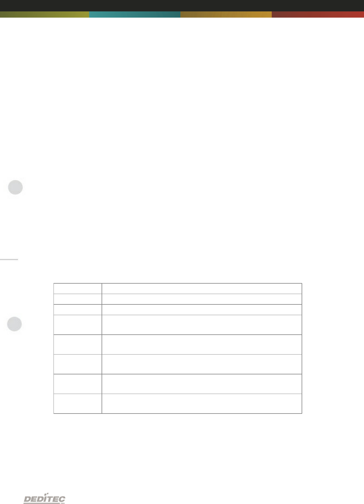
2.2.1.4.1. Definition of LEDs
LED
Description
3,3V
Internal 3,3V power supply
5V
Internal 5V power supply
Interface
Activity
Active communication- over the CAN bus
ERROR
Error during CAN-transfer (for details see document ”CAN
protocol”)
Inputs:
Change
State change between 2 read-out cylces detected
Outputs:
Auto-Off
Due to timeout, all outputs are switched-off for safety
reasons
I/O Access
CPU-access on the inputs and outputs of the connected
modules