
User manual
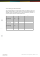
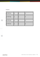
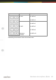
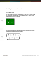
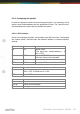
Table Of Contents
- Introduction
- Hardware description
- Software
- Appendix
- manual_e_delib.pdf
- Introduction
- Hardware description
- Software
- Appendix
- manual_e_ro_io_stepper2.pdf
- Introduction
- Hardware description
- Software
- DELIB API reference
- Management functions
- Error handling
- Stepper motor functions
- DapiStepperCommands
- DAPI_STEPPER_CMD_GO_POSITION
- DAPI_STEPPER_CMD_GO_POSITION_RELATIVE
- DAPI_STEPPER_CMD_SET_POSITION
- DAPI_STEPPER_CMD_SET_FREQUENCY
- DAPI_STEPPER_CMD_GET_FREQUENCY
- DAPI_STEPPER_CMD_SET_FREQUENCY_DIRECTLY
- DAPI_STEPPER_CMD_STOP
- DAPI_STEPPER_CMD_FULLSTOP
- DAPI_STEPPER_CMD_DISABLE
- DAPI_STEPPER_CMD_SET_MOTORCHARACTERISTIC
- DAPI_STEPPER_CMD_GET_MOTORCHARACTERISTIC
- DAPI_STEPPER_CMD_MOTORCHARACTERISTIC_EEPROM_SAVE
- DAPI_STEPPER_CMD_MOTORCHARACTERISTIC_EEPROM_LOAD
- DAPI_STEPPER_CMD_MOTORCHARACTERISTIC_LOAD_DEFAULT
- DAPI_STEPPER_CMD_GO_REFSWITCH
- DAPI_STEPPER_CMD_GET_CPU_TEMP
- DAPI_STEPPER_CMD_GET_MOTOR_SUPPLY_VOLTAGE
- DapiStepperGetStatus
- DapiStepperCommandEx
- DapiStepperCommands
- Example program
- Appendix
- manual_e_ro_serie.pdf
- Introduction
- Hardware description
- Ethernet Interface
- CAN Interface
- RS-232/RS-485 Interface
- USB Interface
- Digital in-/output modules
- Analog in-/output modules
- Stepper module
- Software
- DELIB API reference
- Management functions
- Error handling
- Reading Digital inputs
- Setting Digital outputs
- A/D converter functions
- D/A outputs management
- Stepper motor functions
- DapiStepperCommands
- DAPI_STEPPER_CMD_GO_POSITION
- DAPI_STEPPER_CMD_GO_POSITION_RELATIVE
- DAPI_STEPPER_CMD_SET_POSITION
- DAPI_STEPPER_CMD_SET_FREQUENCY
- DAPI_STEPPER_CMD_GET_FREQUENCY
- DAPI_STEPPER_CMD_SET_FREQUENCY_DIRECTLY
- DAPI_STEPPER_CMD_STOP
- DAPI_STEPPER_CMD_FULLSTOP
- DAPI_STEPPER_CMD_DISABLE
- DAPI_STEPPER_CMD_SET_MOTORCHARACTERISTIC
- DAPI_STEPPER_CMD_GET_MOTORCHARACTERISTIC
- DAPI_STEPPER_CMD_MOTORCHARACTERISTIC_EEPROM_SAVE
- DAPI_STEPPER_CMD_MOTORCHARACTERISTIC_EEPROM_LOAD
- DAPI_STEPPER_CMD_MOTORCHARACTERISTIC_LOAD_DEFAULT
- DAPI_STEPPER_CMD_GO_REFSWITCH
- DAPI_STEPPER_CMD_GET_CPU_TEMP
- DAPI_STEPPER_CMD_GET_MOTOR_SUPPLY_VOLTAGE
- DapiStepperGetStatus
- DapiStepperCommandEx
- DapiStepperCommands
- Output timeout management
- Test functions
- Example program
- Appendix

Hardware description |
Seite 45
2.3.1.5. Control LEDs
The RS-232/RS-485 module has a series of control LEDs. They are used for
easy visual indication of various state functions.
While switching the module on in normal operating mode, the module should
signalize the following sequence:
-
all five LEDs flashing briefly
-
right LED (I/O access) flashing briefly
In ”special mode”, the following signal sequence should be seen:
-
all five LEDs flashing briefly
-
right LED (I/O access) flashing briefly
-
all five LEDs flashing briefly
2.3.1.5.1. Definition of LEDs
LED
Description
3,3V
Internal 3,3V power supply
5V
Internal 5V power supply
Interface
Activity
Active communication over the RS-232/RS-485 bus
ERROR
Error during serial-transfer (for details see document ”Serial
protocol”)
Inputs:
Change
State change between 2 read-out cylces detected
Outputs:
Auto-Off
Due to timeout, all outputs are switched-off for safety
reasons
I/O Access
CPU-access on the inputs and outputs of the connected
modules