
User manual
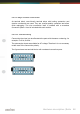

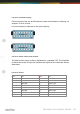
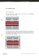
Table Of Contents
- Introduction
- Hardware description
- Software
- Appendix
- manual_e_delib.pdf
- Introduction
- Hardware description
- Software
- Appendix
- manual_e_ro_io_stepper2.pdf
- Introduction
- Hardware description
- Software
- DELIB API reference
- Management functions
- Error handling
- Stepper motor functions
- DapiStepperCommands
- DAPI_STEPPER_CMD_GO_POSITION
- DAPI_STEPPER_CMD_GO_POSITION_RELATIVE
- DAPI_STEPPER_CMD_SET_POSITION
- DAPI_STEPPER_CMD_SET_FREQUENCY
- DAPI_STEPPER_CMD_GET_FREQUENCY
- DAPI_STEPPER_CMD_SET_FREQUENCY_DIRECTLY
- DAPI_STEPPER_CMD_STOP
- DAPI_STEPPER_CMD_FULLSTOP
- DAPI_STEPPER_CMD_DISABLE
- DAPI_STEPPER_CMD_SET_MOTORCHARACTERISTIC
- DAPI_STEPPER_CMD_GET_MOTORCHARACTERISTIC
- DAPI_STEPPER_CMD_MOTORCHARACTERISTIC_EEPROM_SAVE
- DAPI_STEPPER_CMD_MOTORCHARACTERISTIC_EEPROM_LOAD
- DAPI_STEPPER_CMD_MOTORCHARACTERISTIC_LOAD_DEFAULT
- DAPI_STEPPER_CMD_GO_REFSWITCH
- DAPI_STEPPER_CMD_GET_CPU_TEMP
- DAPI_STEPPER_CMD_GET_MOTOR_SUPPLY_VOLTAGE
- DapiStepperGetStatus
- DapiStepperCommandEx
- DapiStepperCommands
- Example program
- Appendix
- manual_e_ro_serie.pdf
- Introduction
- Hardware description
- Ethernet Interface
- CAN Interface
- RS-232/RS-485 Interface
- USB Interface
- Digital in-/output modules
- Analog in-/output modules
- Stepper module
- Software
- DELIB API reference
- Management functions
- Error handling
- Reading Digital inputs
- Setting Digital outputs
- A/D converter functions
- D/A outputs management
- Stepper motor functions
- DapiStepperCommands
- DAPI_STEPPER_CMD_GO_POSITION
- DAPI_STEPPER_CMD_GO_POSITION_RELATIVE
- DAPI_STEPPER_CMD_SET_POSITION
- DAPI_STEPPER_CMD_SET_FREQUENCY
- DAPI_STEPPER_CMD_GET_FREQUENCY
- DAPI_STEPPER_CMD_SET_FREQUENCY_DIRECTLY
- DAPI_STEPPER_CMD_STOP
- DAPI_STEPPER_CMD_FULLSTOP
- DAPI_STEPPER_CMD_DISABLE
- DAPI_STEPPER_CMD_SET_MOTORCHARACTERISTIC
- DAPI_STEPPER_CMD_GET_MOTORCHARACTERISTIC
- DAPI_STEPPER_CMD_MOTORCHARACTERISTIC_EEPROM_SAVE
- DAPI_STEPPER_CMD_MOTORCHARACTERISTIC_EEPROM_LOAD
- DAPI_STEPPER_CMD_MOTORCHARACTERISTIC_LOAD_DEFAULT
- DAPI_STEPPER_CMD_GO_REFSWITCH
- DAPI_STEPPER_CMD_GET_CPU_TEMP
- DAPI_STEPPER_CMD_GET_MOTOR_SUPPLY_VOLTAGE
- DapiStepperGetStatus
- DapiStepperCommandEx
- DapiStepperCommands
- Output timeout management
- Test functions
- Example program
- Appendix

Hardware description |
Seite 60
2.5.1.1.7.1. Changing the input voltage
Each terminal block has 8 inputs sudivided in two groups and each group has its
own input voltage range (resulting groups: 1-4, 5-8, 9-12 und 13-16). Each
group‘s input voltage range is defined by a corresponding resistor network.
The following steps describes how to exchange one or more resistor networks.
Notice!
Bevore opening the device, please note the following:
Disconnect the power supply (unplug AC/DC adaptor)!
Do not touch electronic components. They could be destroyed by electrostatic
discharge! If necessary, touch grounded metal casings or radiators.
Remove a module‘s side element. Unscrew the three Phillips screws.
Pull the circuit board together with the front panel sideways out.
Lift the front panel from the module.
Every input module has two single rowed socket terminal strips in which the
resistor networks are plugged in. Please carefully remove the desired resistor
network and replace them it appropriate one.
Assembling the elements in done the reverse order.