
User manual


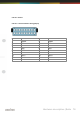
Table Of Contents
- Introduction
- Hardware description
- Software
- Appendix
- manual_e_delib.pdf
- Introduction
- Hardware description
- Software
- Appendix
- manual_e_ro_io_stepper2.pdf
- Introduction
- Hardware description
- Software
- DELIB API reference
- Management functions
- Error handling
- Stepper motor functions
- DapiStepperCommands
- DAPI_STEPPER_CMD_GO_POSITION
- DAPI_STEPPER_CMD_GO_POSITION_RELATIVE
- DAPI_STEPPER_CMD_SET_POSITION
- DAPI_STEPPER_CMD_SET_FREQUENCY
- DAPI_STEPPER_CMD_GET_FREQUENCY
- DAPI_STEPPER_CMD_SET_FREQUENCY_DIRECTLY
- DAPI_STEPPER_CMD_STOP
- DAPI_STEPPER_CMD_FULLSTOP
- DAPI_STEPPER_CMD_DISABLE
- DAPI_STEPPER_CMD_SET_MOTORCHARACTERISTIC
- DAPI_STEPPER_CMD_GET_MOTORCHARACTERISTIC
- DAPI_STEPPER_CMD_MOTORCHARACTERISTIC_EEPROM_SAVE
- DAPI_STEPPER_CMD_MOTORCHARACTERISTIC_EEPROM_LOAD
- DAPI_STEPPER_CMD_MOTORCHARACTERISTIC_LOAD_DEFAULT
- DAPI_STEPPER_CMD_GO_REFSWITCH
- DAPI_STEPPER_CMD_GET_CPU_TEMP
- DAPI_STEPPER_CMD_GET_MOTOR_SUPPLY_VOLTAGE
- DapiStepperGetStatus
- DapiStepperCommandEx
- DapiStepperCommands
- Example program
- Appendix
- manual_e_ro_serie.pdf
- Introduction
- Hardware description
- Ethernet Interface
- CAN Interface
- RS-232/RS-485 Interface
- USB Interface
- Digital in-/output modules
- Analog in-/output modules
- Stepper module
- Software
- DELIB API reference
- Management functions
- Error handling
- Reading Digital inputs
- Setting Digital outputs
- A/D converter functions
- D/A outputs management
- Stepper motor functions
- DapiStepperCommands
- DAPI_STEPPER_CMD_GO_POSITION
- DAPI_STEPPER_CMD_GO_POSITION_RELATIVE
- DAPI_STEPPER_CMD_SET_POSITION
- DAPI_STEPPER_CMD_SET_FREQUENCY
- DAPI_STEPPER_CMD_GET_FREQUENCY
- DAPI_STEPPER_CMD_SET_FREQUENCY_DIRECTLY
- DAPI_STEPPER_CMD_STOP
- DAPI_STEPPER_CMD_FULLSTOP
- DAPI_STEPPER_CMD_DISABLE
- DAPI_STEPPER_CMD_SET_MOTORCHARACTERISTIC
- DAPI_STEPPER_CMD_GET_MOTORCHARACTERISTIC
- DAPI_STEPPER_CMD_MOTORCHARACTERISTIC_EEPROM_SAVE
- DAPI_STEPPER_CMD_MOTORCHARACTERISTIC_EEPROM_LOAD
- DAPI_STEPPER_CMD_MOTORCHARACTERISTIC_LOAD_DEFAULT
- DAPI_STEPPER_CMD_GO_REFSWITCH
- DAPI_STEPPER_CMD_GET_CPU_TEMP
- DAPI_STEPPER_CMD_GET_MOTOR_SUPPLY_VOLTAGE
- DapiStepperGetStatus
- DapiStepperCommandEx
- DapiStepperCommands
- Output timeout management
- Test functions
- Example program
- Appendix
Hardware description |
Seite 68
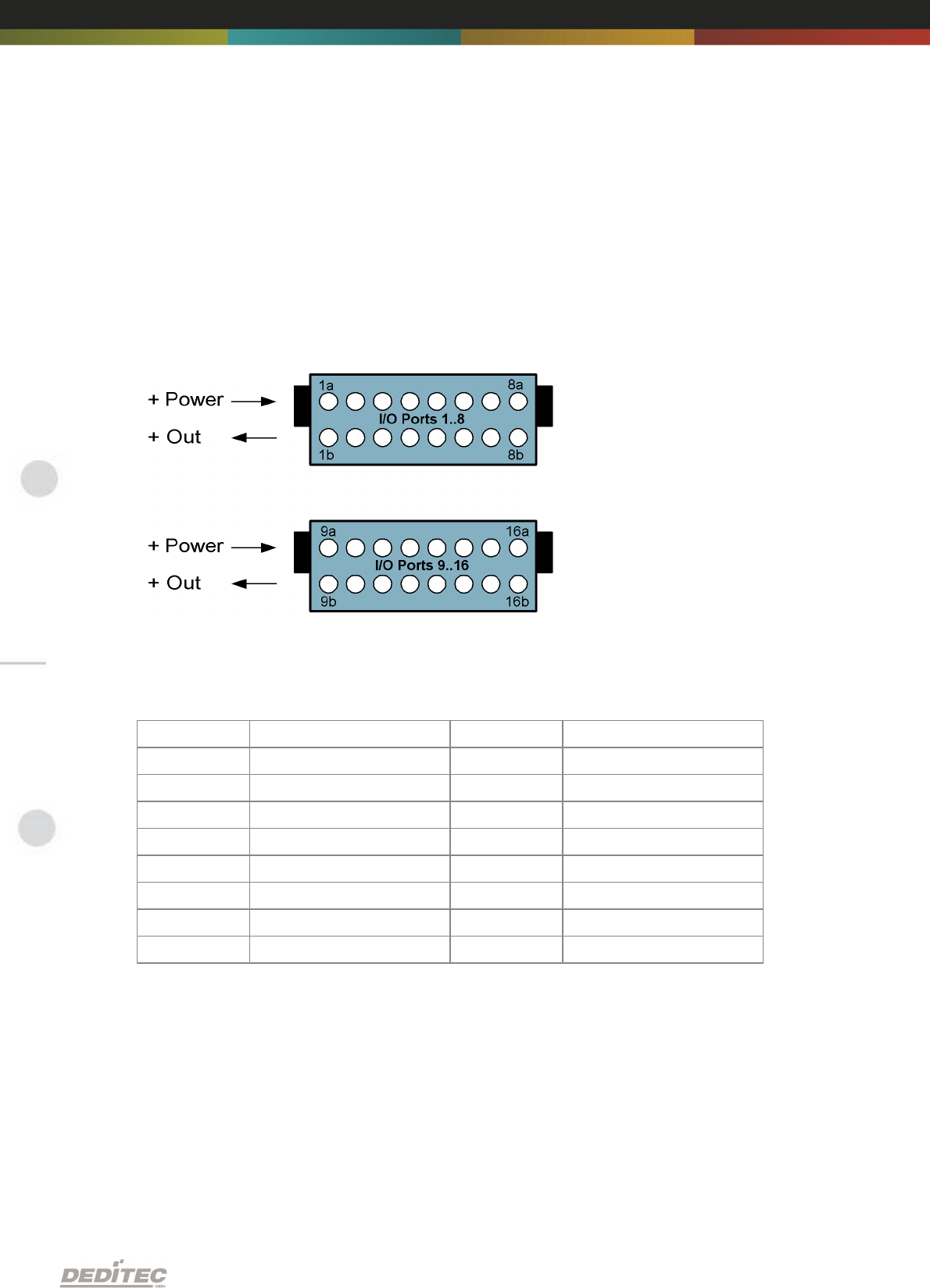
2.5.1.3.4.2. Connection wiring
Connecting the wires is to be effected at the ports with the same numbering, for
example: 1a & 1b, 2a & 2b, ... Pay attention to the optocoupler’s output polarity
while wiring, else the outputs will get damaged. Connect the positive voltage to
port ”a”, and the switched positive voltage to port ”b”.
2.5.1.3.4.3. Pinout
Port
Pin
Port
Pin
1
1a & 1b
9
9a & 9b
2
2a & 2b
10
10a & 10b
3
3a & 3b
11
11a & 11b
4
4a & 4b
12
12a & 12b
5
5a & 5b
13
13a & 13b
6
6a & 6b
14
14a & 14b
7
7a & 7b
15
15a & 15b
8
8a & 8b
16
16a & 16b