
Operating instructions


Issue 10/06 6 Commissioning
MICROMASTER 430
Operating Instructions (Compact)
45
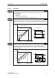
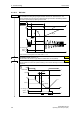
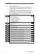
BI: Fct digital output 1
Defines the source for digital output 1.
NOTE
The brake relay can also be controlled from
another digital output (if this is available) or
using a distributed I/O module. Analog to
DOUT 1, it should be guaranteed that the
I/Os are controlled by the status bit “MHB
active”.
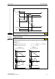
Inverting digital
outputs
This parameter allows the signals
to be output to be inverted.
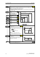
Frequent settings: Closed
52.0 Ready to power-up 0
52.1 Ready 0
52.2 Drive operational 0
52.3 Fault present 0
52.4 OFF2 active (present) 1
52.5 OFF3 active (present) 1
52.6 Power-on inhibit active (present) 0
52.7 Alarm active (present) 0
52.8 Deviation, setpoint/actual value 1
52.9 PZD / PLC control 0
52.A Maximum frequency reached 0
52.B Alarm: Motor current limit 1
52.C Motor holding brake active 0
52.D Motor overload 1
52.E Motor dir. of rotation, clockwise 0
52.F Frequency inverter overload 1
53.0 DC brake active 0
53.1 Actual freq. f_act > P2167 (f_off) 0
:
:
(52:3)
BI: Fct. of DOUT 1
P0731.C
-1
0
1
Invert DOUTs
0 ... 7
P0748 (0)
CO/BO: State DOUTs
r0747
r0747
Kl.20
Kl.18
.0
Function
xxxx.y
rxxxx.y
P0731 = xxxx.y
DOUT channel
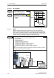
Relay :
DC 30 V / 5 A
AC 250 V / 2 A
Kl.28
Kl.9
int. 24 V
max. 100 mA
NO
COM
NC
Kl.19
or
max. load capability
max. opening / closing time
5 / 10 ms
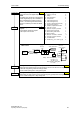
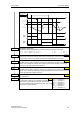
Holding brake release delay (entered in s)
Defines the time interval during which the frequency inverter runs with the min. frequency
p1080 after magnetizing, before the ramp-up starts.
P1216
≥ brake opening time + relay opening time
Holding time after ramp-down (entered in s)
Defines time for which inverter runs at minimum frequency (p1080) after ramping down.
P1217
≥ brake closing time + relay closing time
P1217 = ...
1.0 s
P1216 = ...
1.0 s
0
52.3
P0731=52.C
P0748 = 0