8 Channel H.264 Smart LCD-DVR Security Camera w/ Coaching iMenu and Night Vision Surveillance Cameras INSTRUCTION MANUAL V1.0 SN503-8CH www.defender-usa.
IMPORTANT! PLEASE READ! NEED HELP? DO NOT RETURN THIS PRODUCT TO THE STORE Please contact a DEFENDER customer support representative first regarding any additional information on product features, specifications or assistance with setup. Please contact us via one of the methods below: Email: support@defender-usa.com Online live web chat: Visit www.defender-usa.com Toll free telephone: 1.866.946.7828 Toll free fax: 1.888.771.1701 For more product information visit www.defender-usa.
IMPORTANT! PLEASE READ! PRODUCT WARRANTY INFORMATION Please visit our website at www.defender-usa.com for information about your product’s warranty. We take quality very seriously. That is why all of our products come with a one year warranty from the original purchase date against defects in workmanship and materials. If you have warranty or support issues please contact us using any of the following methods: Phone: 1.866.946.7828 Fax: 1.888.771.1701 Email: support@defender-usa.com Website: www.
TABLE OF CONTENTS TABLE OF CONTENTS............................................................................................... 1 INTRODUCTION..................................................................................................... 3 WHAT IS INCLUDED................................................................................................ 3 FEATURES............................................................................................................. 4 OPTIONAL ACCESSORIES........
TABLE OF CONTENTS PLAYBACK........................................................................................................... 41 Playback through DVR............................................................................................... 41 Computer Playback.................................................................................................... 42 File Viewing.............................................................................................. 43 Software Functions.......
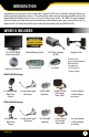
INTRODUCTION Congratulations on your purchase of the Sentinel 503 8 Channel LCD-DVR! This user friendly system will allow you to monitor and protect your home or business. The coaching iMenu makes setting up and using your DVR very easy with helpful information bubbles that assist you in using and setting up your system. The SN503-8CH comes equipped with H.264 compression which allows you to record and store more footage using less space, so you will never miss an important event.
FEATURES View Online or on a Smartphone This system allows you to check on your footage, no matter white time it is or where you are in the world. You have the power to access your DVR’s footage over the internet1 or directly from your iPhone® or BlackBerry ®2 smartphone. All-In-One Security System Sync combines a vibrant 19” LCD monitor with a powerful DVR system. The compact design is sleek, stylish and easy to setup.
FEATURES Expandable up to 8 Cameras This system comes with four cameras and allows you expand it to up to eight cameras total. This allows you to expand your system as your monitoring needs expand, so that you won’t have to purchase an entirely new system. Compatible with any Defender SP5, SP301-C or SP500-C cameras. Included Mouse and Remote Control The Included Mouse and remote control allow you to navigate through the menu easily and hassle free.
BUTTON AND CONNECTIONS 1 LCD-DVR LEFT SIDE 1. 2. 3. 4. 5. 6. 7. 8. Power Connection: LCD-DVR Power Connection LAN Connection: Connects to Router Mouse Connection: Connection for USB Mouse USB Connection: Connection for USB device Audio Out: Connection for audio device Video Out: RCA video out jacks for spot monitors Power Switch: Power on/off switch External I/O Connect “PERIPHERAL CABLE” here 3 4 2 5 6 8 7 1 LCD-DVR RIGHT SIDE 1. Removable HDD: 2 3 4 5 SN503-8CH 2. ON/Off: 3. Menu: 4. Up: 5.
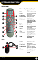
BUTTON AND CONNECTIONS REMOTE CONTROL 1 2 3 5 4 6 7 8 11 9 12 10 13 1. Numerical Keypad: Buttons 1-8 will display the corresponding camera on full screen 2. All: Switch to quad viewing mode 3. Menu: Access the main menu and exit the current menu 4. Select/Enter: Allows you to select options 5. Directional Keys: Allows you to navigate through the menu 6. Audio/Search: Searches and finds any channels that have an audio supported camera attached to it (not included) 7. Mute: Mutes sound 8.
BASIC SETUP THINGS TO CONSIDER BEFORE INSTALLATION • • • • • • • • The camera should be installed between 8 to 13ft above the area to be monitored Decide whether the camera will be wall mounted, ceiling mounted or sitting on a desk/table top.
BASIC SETUP CONNECTING PERIPHERAL CABLE 1. Connect the “PERIPHERAL CABLE” to the jack on the left side of the LCD-DVR named, “EXTERNAL I/O.” 2. With the cable in place, turn the plastic screws clockwise to lock the connection. 3. The “PERIPHERAL CABLE” is where you will connect all of your security cameras, PTZ cameras and alarm system. WIRING CAMERAS A B D C G F H K L J E INSTRUCTIONS 1. Plug 12V adapter (A) into electrical wall outlet or surge protecting power bar. 2.
BASIC SETUP CONNECTING ADDITIONAL DEVICES CONNECTING A USB MOUSE Plug Mouse into USB port Connect the included USB mouse before powering on the SN5038CH. This will speed up the initializing process as well as make the DVR easier to use. 1. Plug the USB connection on the mouse into the top USB connection on the left side of the DVR marked with a mouse icon. CONNECTING A PTZ CAMERA The SN503-8CH supports a 2 wire RS-485 connection for a PTZ camera to be connected (PTZ camera not included).
BASIC SETUP POWERING ON YOUR LCD-DVR 1. 2. Insert the power cord into the power supply. Plug the power cord into a power outlet (surge protected power outlet recommended). 3. Insert the power supply wire into the DC 12V port on the left side of the LCD-DVR. 4. There is a power on/off switch located on the left side of the SN503-8CH, press this down to turn on your security system.
FUNCTION MENU FUNCTION MENU The Function Menu can be accessed two different ways: 1. Right clicking the mouse. From the viewing screen, right click the mouse to access the function menu. As you scroll through the menu with your mouse, you will notice that the option becomes highlighted. Left click to select your desired command or move your cursor away from the menu and left click to close. 2. Pressing select (SEL) on the remote control. Then use the up and down arrow keys to navigate the menu.
SHORTCUT MENU PTZ Camera Selecting this shortcut opens the PTZ menu (PTZ camera not included). PTZ stands for Pan/Tilt/Zoom. This menu option will only control PTZ cameras properly configured in Device Management. To view instructions on how to configure a PTZ camera, please see Connecting a PTZ Camera on page 10.
SHORTCUT MENU Start Record • Selecting this prompts the LCD-DVR to begin manual recording (if it is not already recording). Selecting this will override any set recording schedule Stop Record • Selecting this prompts the LCD-DVR to stop manual recording Start Cruise • Selecting this option prompts the PTZ cruise to start (if you have configured a compatible PTZ camera).
SHORTCUT MENU Digital Zoom When viewing in full screen mode, the function menu features a “Digital Zoom” option. This allows you to select an area to view more closely. To zoom in: 1. From the function menu, navigate to and select “DIGITAL ZOOM.” 2. Left click and hold to drag a square over the area you wish to zoom in. 3. To exit, right click the mouse. MAIN MENU The main menu can be accessed by selecting it from the function menu or by pressing the “MENU” button on the remote control.
MAIN MENU USING THE KEYBOARD The keyboard is used when keying in passwords, names, dates and times. To Operate the Keyboard: 1. Navigate to a desired character and then left click to input your selection. 2. By selecting the “ABC” button the case and type of characters will change. Upper case, lower case and numbers are the options available. 3. To erase a character select the backspace button ( ). 4. When the desired entry has been finished, select the enter key ( ).
MAIN MENU Position This will determine where the title of the camera will be displayed. Selecting “OFF” will provide no title on screen for desired camera. To Change the Position of your Camera’s Name: 1. Under the “POSITION” column, navigate to and select the drop down list of the channel’s name you would like to reposition. 2. Select which quadrant of the screen you want that camera’s title to appear. 3. Repeat for all desired cameras. 4. Select “APPLY” to save changes.
MAIN MENU Time Display The SN503-8CH allows you to select if you would like the time and date displayed while in live view or while recording. To Enable/Disable the Time Display: 1. Select the drop down list next to the time display mode you would like to change. 2. Select “OFF” or “ON.” 3. Select “APPLY” to save your settings. Time Display Options Privacy Zone “PRIVACY ZONE” allows you to set up to four adjustable areas per camera that you wish to mask or remain private.
MAIN MENU Auto Sequence This option allows you to choose the duration for each camera on the screen while in auto sequencing mode; choose anywhere from zero to ten seconds. You can also choose whether to sequence only channels one through four or five through eight for a specific duration. To Adjust Automatic Sequencing: 1. Select “AUTOSEQ” from Camera Setup menu. 2. Navigate to and select desired channel and a drop down list, select desired duration. 3. Select “APPLY” to save settings.
MAIN MENU Audio Rec. To turn audio recording On or Off: 1. Navigate to and select the drop down menu beside “Audio Rec”. 2. Select which camera you would like the audio to record from and press select. 3. Select “APPLY” to save settings. Note: Only audio enabled cameras (sold seperately) are able to record audio. File Size The DVR allows you choose the maximum length that each recorded video clip will be. This is for backup purposes. To adjust and/or set a file size: 1.
MAIN MENU To customize your record schedule : Schedule Menu The SN503-8CH allows you to set different recording schedules and recording types for each individual channel. (Normal record, motion record or no record) 1. From the camera setup menu, ensure that “TIME SCHEDULE RECORD” is selected. 2. Navigate to and select “SCHEDULE.” To adjust the recording schedule: 1. Select the drop down list titled, “CHANNEL.” 2. Navigate to and select which camera you wish to set a schedule for. 3.
MAIN MENU NETWORK SETUP MENU The network setup menu is your gateway to viewing footage online. The SN503-8CH is pre-configured to work with most network setups. The network setup menu allows you to configure all the settings necessary to view your DVR online. You can adjust the way the DVR acquires an IP address, which ports are used to communicate with the DVR, DNS and set information for a DDNS account. Network Menu Type: Determines how the LCD-DVR will acquire and IP address: DHCP, Static IP or PPoE.
MAIN MENU Media Port: This port is used to initiate communication with the LCD-DVR. The media port is entered at the end of the IP address to connect to the DVR. If using the default port (80), your internet browser will automatically add port 80 to the end of the address even though it may not display it. If using a port other than 80, you will need to add that port to the end of the IP address when typing it into a web browser. (Ex. If using port 2000 and IP address is 192.168.1.
MAIN MENU DNS: Domain Name System (DNS) is for advanced network setup. DNS is used to convert names into IP addresses. It is recommended to leave these settings as they will be automatically configured by the router. To adjust the DNS address: 1. Navigate to the DNS address bar, select it to adjust the value. 2. The keyboard will prompt, input the desired address then select the enter key.
MAIN MENU VIDEO SEARCH This option allows you to search through your previously recorded footage organized by date and time. You can access the video search from the main menu, the function menu or by pressing the “PLAY” button on the remote control. To access and play back footage: 1. Select the channel to view recorded footage from (1). 2. Navigate to and select the date to view footage from, (2) this will prompt a keyboard to input date. Once the date has been inserted, select “SEARCH” (3).
MAIN MENU File List The file list allows you to see the type of recording (normal, alarm), date and time footage was recorded, size of footage and the option to backup selected recorded events. File List Menu To access the file from the video search menu: 1. Navigate to and select the channel and date you would like to view footage from. Once completed, select “SEARCH.” 2. The dates that have recorded footage are colored red or green. Navigate to and select the date you wish to view the file list for. 3.
MAIN MENU Backup The SN503-8CH allows you to back up footage onto a USB device such as a USB memory stick, USB HDD or a USB CD/ DVD writer for playback on a computer. To Backup footage onto USB device: Connect USB device into bottom USB port 1. Ensure USB device is connected to the appropriate USB port on the left side of the LCD-DVR. 2. Access the file list for the particular day you would like footage backed up. For more information on the File List, please see page 26. 3.
MAIN MENU HDD This option gives you information about your HDD (Hard Disk Drive), allows you to enable overwrite mode and format the hard drive and/or USB drive. The information this option includes: • HDD Status: Displays the current operating status of the hard drive. If the Hard Drive is functioning normally it will display OK • Total Space: The total size of the HDD • Free Space: How much space is available on the HDD • Usable Rec.
MAIN MENU HDD Format Formatting the HDD erases all recorded video and audio on your Hard Disk Drive. To Format the HDD: 1. Select “FORMAT HDD.” 2. You will be prompted, “All data will be erased, are you sure you want to format?” 3. Select “OK” to format the HDD or “CANCEL” to prevent formatting. 4. It may take a few minutes to format the HDD, you are unable to cancel during this process. 5. Once complete, you will be notified the HDD has been formatted successfully. 6.
MAIN MENU Alarm Setup This menu allows for the adjustment of a variety of alarm types and settings including an internal audible buzzer and email alerts. The SN503-8CH features many types of alarms and alerts.
MAIN MENU PTZ Setup PTZ setup allows you to input information for a PTZ camera (PTZ camera not included). To input the PTZ information: NOTE: Refer to your PTZ camera’s manual for detailed instructions on installation and configuration settings. 1. Input designated information of your PTZ cameras for the appropriate channels. 2. From this menu you can also choose to enable/disable cruise mode for the PTZ camera. 3. When all PTZ related information is entered, select “APPLY” to save changes.
MAIN MENU Motion Detection This menu option allows you to adjust the motion detection settings for each individual camera. The settings you can adjust include turning motion detection on or off, adjusting the sensitivity of motion detection and designating the motion detection area. To change the status of motion detection for each camera: 1. Navigate to and select the “STATUS” drop down list for the camera you would like to turn motion detection on/off. 2.
MAIN MENU MD Area Motion Detection Area allows you to adjust particular areas of each camera where motion will or will not be detected. This is ideal if a camera is pointed in the direction of something that constantly has motion, such as a road, then, only the desired sections will trigger recording saving valuable space on your HDD. To adjust the MD area: 1. Navigate to and select “SETUP” for the channel you would like to adjust the motion detection area. This will prompt the MD Area grid.
MAIN MENU SYSTEM SETUP This menu option allows you to change system settings on your DVR.
MAIN MENU To adjust the date: 1. Select the column next to the date you would like to change and a keyboard will appear. 2. Type the date in the order of the selected format, indicated next to “DATE FORMAT,” then select enter to close the keyboard. 3. Select “APPLY” to save your changes. To adjust the time: 1. Select the text box next to “TIME”. 2. Type the time in the order of the selected format, indicated next to “TIME FORMAT,” then select enter. 3. Select “APPLY” to save your changes.
MAIN MENU Daylight Savings Time (DST) You can adjust the SN503-8CH to change automatically when daylight savings time occurs, or, at your scheduled preference. To set the LCD-DVR to adjust for daylight savings time automatically: 1. Select the drop down list “DST,” select “ON.” 2. Select the drop down list, “DST MODE,” select “DEFAULT.” 3. Select “APPLY” to save your changes. To customize the LCD-DVR daylight savings time adjustment: 1. Select the drop down list “DST,” select “ON.” 2.
MAIN MENU Password Setup This menu selection allows you to change the device ID, enable password protection as well as set a new password for users and admin on your DVR. When you enable password protection, you will be prompted to input a password each time you wish to access the main menu. The default password is set to 123456.
MAIN MENU Video Setup This menu option allows you to select the video format of your DVR. To adjust your video system: Geographically, throughout the world, there are two common video formats: NTSC and PAL. National Television System Committee (NTSC) is the commonly used format for North America and Japan. Phase Altering Line (PAL) is the common format in European nations. The SN503-8CH is automatically configured to NTSC. To change the video system: 1. Select the drop down list next to “VIDEO SYSTEM.” 2.
MAIN MENU Language The SN503-8CH allows you to set different languages. The included languages are: English, German, Italian, Russian, French, Spanish, Portuguese, Polish and Danish. Language Setup (English only) To adjust the language: 1. Select the drop down list, “SYSTEM LANGUAGE.” 2. Select desired language. 3. Select “APPLY” to save your changes. Note: Changing languages will restart the system System Information This area allows you to view information about your LCD-DVR.
MAIN MENU System Maintenance System maintenance allows you to load system default settings, set up your LCD-DVR for automatic maintenance, adjust system reboot, manually reboot the system as well as update the system with a USB device. To enable auto-maintenance: 1. Select the drop down list, “AUTO MAINTAIN.” 2. Select auto-maintenance “ON” or “OFF.” 3. Select “APPLY” to save your changes. To configure auto reboot: 1. Select the drop down list next to “AUTO REBOOT.” 2.
PLAYBACK Playback Screen PLAYBACK Once you have selected the footage you would like to view, it will automatically play. Upon play back, options on the bottom of the screen appear for you to manipulate the video. These options are also easily accessible with the remote control. The options and their functions are as follows: (from left to right on the screen) 1. Rewind: Pressing this rewinds the footage, the more times you press this the faster the footage will rewind (x2, x4, x8). 2.
PLAYBACK COMPUTER PLAYBACK When you backup footage onto a USB device you can view it on your computer. This allows you more options for manipulating video and to back it up directly to your computer. To view footage though your computer: 1. Insert included software CD into disk drive and double click to install the playback software. 2. Follow the installation guide until the end. 3. Once everything has been successfully installed, insert USB device into USB port on computer.
PLAYBACK File Viewing Instructions differ depending on what file(s) you would like to open and play: → → → → One Video 1. Select “File” →”Open Local File”. Find the USB device file, or any other area where backed up footage would be stored on your computer. 2. Make sure to view . 264 Files. 3. Select the file you would like to view and select “open”. 4. Once you have selected open, the video will NOT play automatically. You must prompt the video to play. 5.
PLAYBACK Software Functions The software has many functions. The drop down menus allow you to adjust the video, the file menu allows you to open video files, and settings allows you to adjust certain settings in the software.
PLAYBACK Software Playback Functions If you navigate towards the bottom of you computer screen, the playback bar will expand: 1. Minute Bar: 2. Hour Bar: 3. Hour Forward: 4. Capture Picture: 5. Date: 6. Time: 7. Date and Speed: 8. 9. 10. 11. 12. 13. 14. 15. Play: Backwards: Pause: Stop: Backward Frame: Forward Frame: Rewind: Fast Forward: 16. 17. 18. 19. 20. Max/Min: Decrease Screen: All: Increase Screen: ST: 21. (i)/OSD: 22.
PLAYBACK To save a section of video: 1. Move the cursor (on the green bar) to the section of footage you would like to save. 2. Select the ST icon. A blue bar will appear where you want the video to start saving as well as make the icons next to the ST icon usable. 3. To cut footage and save it select the scissor icon next to ST and a time range screen should appear. Type in the year, month, day and time you would like to start and stop saving the footage, then select “OK.” A Browse screen will appear.
PLAYBACK Processor Amplification Control This area allows you to adjust the Brightness, Contrast, Hue and Saturation of the playback video. To adjust the video settings: 1. Open up “Processor Amplification Control”, under the settings menu. 2. Move the bar along the line to make the Brightness, Contrast, Hue and Saturation settings higher or lower. 3. When the settings are adjusted to your liking, select OK.
NETWORK GUIDE REQUIREMENTS You will need to have: The DVR connected to a router The router connected to the Internet A PC or laptop that is connected to the same router as the DVR. The PC can be connected by a wired or wireless connection Internet Explorer 6.0 or higher (to check your version of Internet Explorer open I.E. In the top Menu bar select “Help” and then select “About Internet Explorer”. The version of I.E. will be displayed.
NETWORK GUIDE Finding your DVR’s IP Address By default, the DVR IP mode is set to DHCP. This means the SN503-8CH will automatically retrieve an IP address from the router that it is connected to. Unless your network requires a static IP address, leave the IP mode set to DHCP. 1. Access the main menu then navigate to and select “NETWORK SETUP.” 2. Make sure the “IP Mode” is set to DHCP. This setting is acceptable for most users.
NETWORK GUIDE Method 1: 1. Open up Internet Explorer. 2. Click on TOOLS. 3. Click on INTERNET OPTIONS. 4. Click on the SECURITY tab then the CUSTOM LEVEL button. 5. Change the ActiveX settings listed below.
NETWORK GUIDE Method 2: Add the DVR’s IP address to the Trusted Sites in Internet Explorer. 1. Open up Internet Explorer. 2. Click on TOOLS. 3. Click on INTERNET OPTIONS. 4. Click on the SECURITY Tab. 5. Click on TRUSTED SITES. 6. Click on the SITES button. 7. Type in the IP address of the DVR in the following format: http://192.168.0.108 and click ADD. 8. If “Require server verification (https:) for all sites ...” is selected you will need to uncheck the selection box.
NETWORK GUIDE Log in to the DVR (Using Internet Explorer): By default the DVR will require a user to input a password before being able to view the DVR online. The default password for the web interface of the DVR is: 123456 Installing the ActiveX controls: There will be a yellow information bar that pops up below the address bar in Internet Explorer. Click on the yellow information bar and then select “Install This Add-on for All Users on This Computer…”.
NETWORK GUIDE VIEWING YOUR DVR OUTSIDE OF YOUR NETWORK Now that you have successfully viewed your DVR and cameras from a computer connected to the same router it is time to set up your router to view the DVR while at a remote location. This process is called “Port Forwarding” and you can find detailed instructions on how to complete the required steps at: Option 1 www.defender-usa.com/network Option 2 www.portforward.
NETWORK GUIDE OPTION 1: (recommended) This option gives you an audio enabled video that has step-by-step instructions on how to port forward your DVR for your specific router. 1. Open up your web browser and go to: www.defender-usa.com/network 2. Once the site has loaded you will see a list with photos of different DEFENDER DVR models, select the SN503-8CH. 2. You will then see a list with photos of different types of routers. Select the router most similar to yours. 3.
NETWORK GUIDE OPTION 2: 1. Open up your web browser and go to: www.portforward.com 2. Once the site has loaded, scroll down to the large list of routers. 3. Find the type of router you have and select it. • If you cannot find your exact router, select one that is similar to your router or made by the same company that made your router 4. Once you select a router an advertisement will appear – select the “click here to skip this advertisement” text in the top right corner. 5.
NETWORK GUIDE TESTING PORT FORWARDING If you would like to see if your port forwarding worked, follow these steps : 1. Open a web browser and type in www.whatsmyip.org. 2. Your External IP address will be listed on the top center of the screen, make sure to write it down. This is the address that you can use when not at home to connect onto your DVR. 3. Open another web browser. 4. Type in www.canyouseeme.org. This site also allows you to see your external IP address. 5.
NETWORK GUIDE IF YOU CANNOT CONNECT If the remote viewing does NOT connect it could be due to one of the following issues: • Make sure the browser is Internet Explorer 6.0 or higher and is on a Windows PC • Make sure you forwarded both port 80 AND 9000 for TCP and UDP • Make sure you properly installed of the controls (selected the yellow pop-up bar and ran all controls) • Check all your network connections and go through the above steps again to make sure a configuration error was not made.
NETWORK GUIDE TO VIEW ONLINE SOFTWARE USING EXTERNAL IP ADDRESS 1. Open your Internet Explorer and type in www.whatsmyip.org and press enter. This will direct you to a website that lists your external IP address on the top of the page. Write down your external IP address. 2. Open another Internet Explorer window and type in your external IP address, followed by the port you forwarded for your DVR in the following format. http://74.123.3.34:80. 3. Follow the login screen for your DVR.
NETWORK GUIDE DynDNS SETUP The following instructions are for DYNDNS.org setup 1. On a computer that is connected to the same router as the DVR, open a web browser and type www.dyndns.org in the address bar. 2. Create a new account by clicking the “Create Account” link in the top right hand corner of the site. 3. Enter your preferred user name, email address, and password. 4. Optional information can be left blank, unless you would like to enter it. 5.
NETWORK GUIDE LOG INTO THE ACCOUNT AND SETUP A DDNS HOST To set up a DynDNS name for your DVR: 1. Enter the DYNDNS.org user name and password you created and click login. 2. Click on the “Services” button located on the menu bar. 3. Click on the “Dynamic DNS” link. 4. Click on the “Get Started” link located on right side of the screen. 5. Type in a desired host name. We recommend you use your name, family name or your business’ name, as long as it is easy to remember. 6.
NETWORK GUIDE TO VIEW DVR THROUGH HOST NAME 1. Ensure that all your DYNDNS account information is entered into your DVR’s DDNS setup screen. 2. Open Internet Explorer and type in your DVR’s host name that you created on your DYNDNS account. 3. You will be prompted for a Password. Default Password: 123456 4. Click OK and the DVR software and footage will appear.
ONLINE SOFTWARE This is what the online viewing software will look like in live view: Just like the DVR menu, submenus have certain functions that have the same meaning: • Next: • Default: • Apply: • Exit: SN503-8CH Allows you to adjust settings for cameras 5-8 To restore all settings to the default settings select the “Default” button on the bottom of the screen To save changes select “apply” at the bottom of the screen To exit the menu, select “exit” at the bottom of the screen 62
ONLINE SOFTWARE Live Mode The fist tab along the top of the screen for the online viewing allows you to view the DVR in live mode. From this mode the buttons along the side and their functions are as follows: 1. PTZ Camera Controls: Selecting this function opens up PTZ control menu. For more information see “PTZ options” on Pg 67 2. Cruise Setup: This function allows you to setup directions for the PTZ to follow, the PTZ camera will cruise through your set positions and times.
ONLINE SOFTWARE PTZ OPTIONS The controls for the PTZ camera are as follows: Zoom: Pressing the + zooms in and pressing the – zooms out Focus: Pressing the + focuses the picture and pressing the – takes the focus away, many PTZ cameras do this automatically Iris: Pressing the + lets in more light and pressing the – takes light out of the picture, many PTZ cameras do this automatically Directional Keys: Clicking on the directional arrows moves the camera around To set up cruise: 1.
ONLINE SOFTWARE PLAYBACK This tab allows you to search, view and backup previously recorded footage that is stored on your LCD-DVR’s HDD. You can also narrow down your search by type of footage and what camera it was recorded from. To search through footage: 1. Select the date you would like to view the footage from on the calendar by double clicking on the particular date. If the date has available footage, it will be in bold. 2.
ONLINE SOFTWARE Playing Back Footage: When you prompt video to play it may take a few minutes to load but it will play automatically. The playback options (from left to right) are as follows: SN503-8CH Pause/Play: Pauses playback. If the video is currently paused, selecting this button again will prompt the video to play Stop: Stops the footage from playing, prompts a blank screen. Selecting play, after you have stopped the footage, will play the selected footage from the beginning F.
ONLINE SOFTWARE SETUP This tab allows you to go through particular settings and make adjustments to the LCD-DVR. The menu options you can adjust include: • Record • Alarm • PTZ • Network • Setting • Host Info Each function works much like the menu option on the DVR. Record Mode The DVR allows you to choose whether it always records, or if it records based on a schedule that you set up yourself. To program your DVR to always record: 1. Select the drop down menu beside “Record Mode”. 2.
ONLINE SOFTWARE To change the schedule: 1. At the bottom of the schedule area, select the type of recording you would like to insert at particular days and times and press select. • (Red): Alarm record: Records when motion or alarm is detected • (Green): General Record: Constantly records • (White): No Record 2. In the schedule area, click on the day and time you would like to adjust (to record, alarm record or no record). The time slot will fill with the corresponding color. 3.
ONLINE SOFTWARE Alarm Setup The alarm menu on the online software allows you to adjust for motion detection, motion detection area and motion detection sensitivity. Motion Detection This menu option allows you adjust the motion detection settings for each individual camera. The settings you can adjust include turning motion on or off, adjusting the sensitivity and selecting the motion detection area. To change the status of motion detection for each camera: 1.
ONLINE SOFTWARE PTZ Setup PTZ setup allows you to input information for the connected PTZ camera. (PTZ cameras not included). The information must be setup according to the PTZ camera so that the DVR and online software works with your PTZ camera and all its functions. To input the PTZ information: 1. Find which camera channel the PTZ camera is hooked up to and from that row, select the proper information for each PTZ camera connected from the drop down menu on your DVR. 2.
ONLINE SOFTWARE Settings This tab allows you to adjust general settings for your online viewing software and DVR. The settings you can adjust include the Internet bandwidth, the file save path, password enable, changing the password, and daylight savings adjustment. Internet Bandwidth Internet bandwidth is the transmission speed of your connection to the Internet. You need to know your bandwidth speed when changing this setting. To see what your bandwidth is you can go to www.bandwidthplace.
ONLINE SOFTWARE Password Setup This menu selection allows you to enable password protection as well as set a new password for the user and admin accounts on your DVR. To enable password protection: 1. Select the scroll bar next to “password enable” and list will appear. 2. Select to turn the password enable to “on”. 3. Select “apply”, to save your changes.
ONLINE SOFTWARE Host Info This area shows you information about your DVR system. The information you view cannot be changed. HDD Status: Shows you how much space (in GB) you have available on your HDD Available Time: The available recording time you have left on the HDD (in hours) Soft Version: This area shows you the software version of the online viewing software Mac Address: This is the DVR identification 500G 7 LOGOUT Clicking on this tab logs you out of the online software and DVR viewing.
MOBILE VIEWING MOBILE VIEWING This DVR is compatible with iPhone®, BlackBerry®, Windows Mobile® and Symbian ®operating systems on 3G networks. Before you can access your DVR on a mobile phone you must make sure that the DVR has the proper network settings, has been port forwarded, and that you have the proper viewing software on your phone. Set User name, password and port on DVR: 1. Go to Mobile setup on the DVR. 2. Insert the user name and password which a mobile user would use to access the DVR footage.
MOBILE VIEWING 4. Once all the proper information has been entered on your iPhone® and on your DVR. Press the Back button in the top left corner of the iPhone® screen. 5. Press the play button in the bottom left of the screen to start playing live footage from your DVR. 6. Fore more information on the ASee, please review the buttons and connections below. BUTTONS AND CONNECTIONS 1. Viewing Screen 2. Channel Selection Keys 3. PTZ Controls 4. Play & Pause 5. Full Screen 6. Snapshot 7.
MOBILE VIEWING Host: Port: Input your DVR’s IP address Input the port you forwarded for your mobile setup.
MOBILE VIEWING 7. Once the correct information has been inserted, select “OK” and a separate screen viewing your selected channel will appear. 8. The mobile software allows you to change channels, control a PTZ camera as well as capture a video. 9. If you capture a picture it will be stored in the same file location the program was installed. 10. You can convert normal display to full screen display by clicking the screen from on mobile device. Symbian Mobile® From your computer: 1.
TROUBLESHOOTING The cameras are not sequencing • Check if you have sequence turned on under the camera menu options • You must initiate the sequencing to get it to start by right clicking and selecting start auto sequence from the sub menu.
TROUBLESHOOTING Cannot power off LCD-DVR • The DVR will run as long as it is plugged in and power switch is set to on. Flip power switch to off or remove plug to turn off power to LCD- DVR The schedule is not recording properly to my set times • Check to see if you have the proper time set on your DVR. Refer to the instruction manual under System → Date and Time (Pg.
TROUBLESHOOTING • Sometimes your router will not allow you to view the footage with your external IP address because the DVR is hooked up to the same router.
SPECIFICATIONS Video System...............................................................................................NTSC / PAL Video Compression Format...........................................................................H.264 Video Input (Composite Video Signal 1 Vp-p 75Ω BNC) . ..............................8 Channels Video Loop Output (Composite Video Signal 1 Vp-p 75Ω BNC).....................No Video Output......................................................................................
SPECIFICATIONS Web Interface............................................................................................... Licensed software AP, IE browser Remote Alarm Notification............................................................................ Email Alerts Network Protocol.......................................................................................... TCP/IP, PPPoE, DHCP and DDNS, 3G IR Receiver.........................................................................................
WHAT IS INCLUDED 4 x Indoor/Outdoor Night Vision CCD Color Cameras 4 PIN DIN to RCA (male) Video/Power Wire • BNC to RCA Connector • 1 Power Adapter for Camera • Mounting Hardware 4 Port Power Supply for Cameras • 1 Year Warranty • Online/Toll Free Support FEATURES SP301-C Camera 1 1. Sun Shield: 2. 2 3. 4 3 4. 5. 6. 5 One to Four Power Supply Cable 6 1 2 SN503-8CH Helps prevent glare from bright lights Infrared (IR): LEDs allow the camera to see in the dark up to 15ft away.
WIRING ADDENDUM A B D C G F H K L J E WIRING INSTRUCTIONS 1. Plug 12V adapter (A) into electrical wall outlet or surge protecting power bar. 2. Plug the single end of the four port power supply (C) into the male end of the 12V adapter (B). 3. Connect the 4PIN DIN female connection on the camera (E) into the 4PIN DIN male connection on the 60ft video power wire (F). 4. Plug the power jack (G) from the 60ft video/power wire into one of the ports of the four port power supply (D). 5.
CAMERA Specifications SP5 - CMOS Night Vision Camera Camera Type ���������������������������������������������������������������������������������������������������������� Weather Resistant Color CMOS IR Bullet Camera Image Sensor......................................................................................................... 1/4" Color Sharp CMOS Resolution.............................................................................................................. 400 TV Lines Outdoor Use.........
CAMERA Specifications SP301-C - CCD Night Vision Camera Camera Type........................................................................................................... Weather resistant Color IR .............................................................................................................................. CCD Camera Image Sensor......................................................................................................... 1/4" Color SHARP CCD Resolution....................
CAMERA Specifications SP500-C - CCD Long Range Night Vision Camera Camera Type........................................................................................................... Color IR CCD Camera Image Sensor......................................................................................................... 1/4" Sony Color CCD Resolution.............................................................................................................. 420 TV Lines Number of IR LEDs and Range.......
CAMERA TROUBLESHOOTING Before contacting technical support, please follow the troubleshooting tips below for solutions to common problems. Email: support@defender-usa.com Toll free telephone: 1.866.946.7828 Toll free fax: 1.888.771.1701 Online live web chat: Visit www.defender-usa.com No picture/signal Picture is too bright Picture is too dark Night Vision is not working SN503-8CH • Make sure your TV/monitor is on the correct video input channel. This is NOT channel 3.
REPLACEMENT PARTS If you accidentally damage or lose any parts they can be replaced with ease. The following are parts that came with your system and their reference model numbers so you can continue to effectively monitor your premises. PRODUCT MODEL# DFW61 ACC-BNC ACC-SQUID-4TO1 SOFTWARE/ MANUALS DESCRIPTION 4 PIN DIN Cable BNC to RCA Connector Four-to-One Power Supply Your product software and manual are available for download at: http://www.defender-usa.com/downloads.
VISIT US ON THE WEB! ► Product Information ► Specification Sheets ►User Manuals ► Software Updates ► Quick Start Guides ► Firmware Upgrades www.defender-usa.com Disclaimer Defender does not endorse the use of any Defender products for illegal activities. Defender is not responsible or liable in any way shape or form for any damage, vandalism, theft or any other action that may occur while a Defender product is in use by the consumer. www.defender-usa.