SLRSZ1EìWh.
TABLE OF' CONTENTS SECTION ...................................................................................................... Introduction General Specification Data ................................................................................... Engine Tuning Data.. .......................... .I!.............................................................. ..................................................................................... Torque Wrench Settings..
BOOK ONE CONTENTS Section Number Page - Repairsand replacement parts - Poisonous substances -Fuel handling precautions -Fuel tank draining and repair J -Service tools - Location El of vehicle identification numbers 6 GENERAL SPECIFICATION DATA -V8 engine data -2.25 litre petrol engine data -2.25 litre petrol engine data -2.25 litre dicscl cnginc data - 2.
Book One Contents (cont’d) Section 07 GENERAL FITTING INSTRUCTIONS - Precautionsagainst damage -Safetyprecautions - Preparationand dismantling - Inspectionof components -Ball and roller bearings - Oil seals - Jointsand joint faces -Flexible hydraulic pipes and hoses -Metric bolt identification - Metric nut identification - Hydraulic fittings - Keys and keyways - Tabwashers, split pins, nuts and locking wire - Screw threads - Unified thread identification 1091 RECOMMENDED LUBRICANTS, FLUIDS AND CAPACITIE
01 INTRODUCTION fi;y:i: ... :.?" .,:..._;..'...,., . , ... , .!I,.. I :I. This Workshop Manual covers the Land Rover Ninety and One Ten range of vehicles. It is primarily designed to assist skilled technicians in the efficient repair and maintenance of Land Rover vehicles. Using the appropriate service tools and carrying out the procedures as detailed will enable the operations to be completed within t h e time stated in the 'Repair Operation Times'.
lo1I Always have a fire extinguisher containing FOAM CO? GAS, o r POWDER close at hand when handling or draining fuel, o r when dismantling fuel systems and in areas whcre fuel containers are stored. Always disconnect the vehicle battery BEFORE carrying out dismantling or draining work on a fuel system.
- Special Service Tools The use of approved special service tools is important. They are essential if service operations are to be carried out efficiently, and safely. The amount of time which they save can be considerable. Every special tool is designed with the close co-operation of Land Rover Ltd., and no tool is put into production which has not been tested and approved by us.
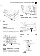
LOCATION OF VEHICLE IDENTIFICATION AND UNIT NUMBERS VEHICLE IDENTIFICATION NUMBER (VIN) The Vehicle Identification Number and the recommended maximum vehicle weights are stamped on a plate riveted to the top of the brake pedal box in the engine compartment. The number is also stamped on the right-hand side of the chassis forward of the spring mounting turret. Always quote this number when writing to Land Rover Limited.
LOCATION OF VEHICLE IDENTIFICATION AND UNIT NUMBERS 01 Y ST664M TRANSFER GEARBOX LT230T - 4 CYLINDER AND V8 VEHICLES FROM SERIAL NUMBER SUFFIX ‘B’ ONWARD ST663M FRONT AXLE Stamped on top of the left-hand axle tube. REAR AXLE Stamped on rear of left-hand axle tube. MAIN GEARBOX LT77 -4 CYLINDER VEHICLES Stamped on a pad on the right-hand side of the gearbox immediately below the oil filler level plug.
GENERAL SPECIFICATION DATA .. ENGINE Type ................................................................. Number of cylinders ............................................. Bore ................................................................. Stroke ............................................................... Capacity ............................................................ Valve operation.. ................................................. Maximum power- B.H.P ...................................
1041 . GENERAL SPECIFICATION DATA Piston rings Number of compression ..................................... Number of oil .................................................. No. 1 compression ring ....................................... No. 2 compression ring.. ..................................... Width of compression rings ................................. Compression ring gap ........................................ Oil ring type .................................................... Oil ring width. .....
GENERAL SPECIFICATION DATA i’. ,. ‘1 ’. ,+ < 1041 2.25 LITRE PETROL ENGINE 1 . ..... ..... .I. ., ENGINE Type ................................................................. Bore ................................................................. Stroke ............................................................... Capacity ............................................................ Valve operation. .................................................. Compression ratio.. ............................
104 I GENERAL SPECIFICATION DATA Piston rings Compression ................................................... Gap in bore .................................................. Clearance in groove.. ...................................... Oil control ...................................................... Gap in bore .................................................. Clearance in groove.. ...................................... 2 0,38 - 0 3 0 mm (0.015 - 0.020 in) 0,046 - 0,097 mm (0.0018 - 0.
GENERAL SPECIFICATION DATA ...... .;-.... .).,..,*.. ..:...: .. :.. Lubrication (continued) Oil pump: Latest type Type ........................................................... Drive .......................................................... End-float of both gears ....................................... Radial clearance of gears ................................. Backlash of gears.. ......................................... Oil pressure relief valve Type ...............................................
104 I GENERAL SPECIFICATIONDATA Gudgeon pins Type .............................................................. Fit in piston ..................................................... Clearance in connecting rod ................................ Floating Push fit by hand 0,007 - 0,015 mm (0.0003 - 0.0006 in) Pistons Type 8.0:1 compression ratio ............................... Clearance in bore measured @ 17 mm from bottom of skirt at right angles to gudgeon pin: Standard and oversize pistons ..............
GENERAL SPECIFICATION DATA ,,:?.% .... 7 Valve springs Type .............................................................. Inner: Length, free ................................................ Length, under 8,0 kg (17.7 Ib) load .................... Outer: Length, free ................................................. Length, under 21 kg (46 Ib) load ........................ Lubrication System ........................................................... System pressure, engine warm at 2000 rpm ...........
GENERAL SPECIFICATION DATA -. Connecting rods Type .............................................................. Length between centres ...................................... Horizontally split big end, plain small end 175,38 - 175,43 mm (6.905 - 6.907 in) Big end bearings Type and material ............................................. Diametrical clearance ........................................ End-float on crankpin. .......................................
GENERAL SPECIFICATION DATA Camshaft Location ......................................................... End-float ........................................................ Number of bearings ........................................... Material ......................................................... Drive ............................................................. Valve springs Type .............................................................. Inner: Length, free .........................................
04 . GENERAL SPECIFICATION DATA Main bearings Number and type.. ............................................ Diametrical clearance ........................................ 5 halved shells 0,018 - 0,061 mm (0.0007 - 0.0024 in) Connecting rods Length between centres.. .................................... Diametrical clearance (big-end bearings). ............... End-float on crankpin ........................................ 175,38 - 175,43 m m (6.905 - 6.907 in) 0,025 - 0,075 mm (0.001 - 0.
GENERAL SPECIFICATION DATA .,: -, Valve springs Type .............................................................. Inner: Length, free ................................................. Length, under 8,O kg (17.7 lb) load .................... Outer: Length, free ................................................. Length, under 21 kg (46 lb) load ........................ , . . a - d r,y;:.:;>:! .r':."'" .._ ..,..I - .._ . . .A
104I GENERAL SPECIFICATION DATA - FUEL SYSTEM VS engine Carburetter ........................................................ Fuel pump - Make,type ...................................... Air cleaner.. ....................................................... See ‘ENGINE TUNING DATA’ Facet, electric mounted vertically on R.H. side of chassis Cyclonc, replaceable element - COOLING SYSTEM 2.25 Petrol, 2.25 and 2.5 Diesel Type.. ...............................................................
GENERAL SPECIFICATION DATA 04 ....... .,- ,.. ......... 4 c,:. i. ^. -; ;, .d ..... ..,, .>,.,. 3:. Main gearbox Type LT77 ...................................................... Speeds ........................................................... Synchromesh ................................................... Ratios: Fifth ........................................................... Fourth (direct) .............................................. Third .....................................................
04 GENERAL SPECIFICATION DATA - TRANSMISSION Ninety and One Ten VS with 5-speed gearbox Main gearbox Type -Manual.. .............................................. LT85 5-speed helical constant mesh, with synchromesh on all forward gears Main gearbox ratios.. ......................................... Fifth (Cruising gear) 0.7951 Fourth 1.oooo Third 1.4362 Second 2.1804 First 3.6497 Reverse 3.8242 Transfer gearbox Type.. ............................................................ -Ninety models .........
GENERAL SPECIFICATION DATA */-: 6 - * :”** SUSPENSION -All Models Type ................................................................. Front ................................................................ Rear ................................................................. BRAKES 2.25 Petrol and V8 Engine System ..............................................................
(047 - GENERAL SPECIFICATION DATA STEERING -All Models Type: Manual -Early Models only ................................. Manual.. ............................................................ Optional power assisted -Early Models.. ................. Optional power assisted -Later Models.. ................. Ratios: Manual Burman straight ahead ............................... Manual Gemmer ................................................. Power assisted straight ahead. .................................
GENERAL SPECIFICATAION DATA , .,..:.-,.:.;: .. ":. ?: ,:I .- ,,,. ,!Z', . I. Alternator - 2.25 litre Petrol and Diesel and 2.5 Diesel Type .............................................................. Maximum D.C. output at 6000 rpm ....................... Rotor -winding resistance ................................. Stator -winding resistance per phase ................... New brush length .............................................. Renew brush at ................................................
04 GENERAL SPECIFICATION DATA Wiper motor -All Models Type .............................................................. Armature end-float ........................................... Minimum brush length.. ..................................... Lucas 14W uprated two-speed 0 , l - 0,20 mm (0.004 - 0.008 in) 4,8 mm (0.190 in) Distributor - All Petrol engines .............................. Coil -All Petrol engines .......................................
GENERAL SPECIFICATION DATA 04 L TYRE PRESSURES Tyres -size and type 6.00-16 CROSS-PLY 7.50-16 CROSS-PLY 205R16 RADIAL-PLY 7.50R16 RADIAL-PLY 7.50-16 CROSS-PLY 750R16 RADIAL-PLY bar Ibf/in2 kgf/cm2 bar Ibf/in2 kgf/cm2 bar Ibflin2 kgf/cm2 bar lbf/inZ kgf/cm2 bar Ibf/in* kgf/cm2 bar Ibf/in2 kgf/cm2 Normal All load conditions Rear Front 2.4 3,25 35 47 2.5 393 19 2,4 28 35 2,o 2.5 19 2,4 28 35 2,O 295 19 2,75 28 40 23-3 2,8 19 2,9 28 42 28 3,O 19 373 28 48 2.0 3.
1041 GENERAL SPECIFICATION DATA VEHICLE WEIGHTS AND PAYLOAD Payload figures quoted in the accompanying table are nominal values for a base specification vehicle and will in general represent the maximum, as any options or extras fitted to the vehicle will increase its unladen weight and hence decrease its allowable payload.
ENGINE TUNING DATA 105I V8 PETROL ENGINE TUNING DATA (with 4-speed gearbox and without electronic ignition) ..... 1 .I. ,' .. ENGINE Compression ratio.. .............................................. Firing order ........................................................ Cylinder numbering system, front to rear: Left bank ........................................................ Right bank ...................................................... Compression pressure (minimum) ...........................
05 ENGINE TUNING DATA DISTRIBUTOR Makehype. ......................................................... Rotation of rotor ................................................. Dwell angle ........................................................ Contact breaker gap ............................................. Condenser capacity .............................................. Centrifugal advance range and capsule.. .................... Vacuum advance capsule range ...............................
ENGINE TUNING DATA 05 L V8 ENGINE TUNING DATA (Ninety and One Ten V8 with 5-speed gearbox and electronic ignition) ,::7. ,, <,.;,: . '." . .+.: ..... ' AUSTRALIA ENGINE Compression ratio.. .............................................. Valve timing Opens ............................................................ Closes ............................................................ Duration ......................................................... Valve peak ..........................................
05 ENGINE TUNING DATA 1 CARBURETTERS Type ................................................................. Solex specification number.. ................................... Needle .............................................................. Idle speed (engine hot).. ........................................ Fast idle speed (engine hot) .................................... Mixture setting - COat idle .................................. IGNITION Distributor makehype.. ....................................
ENGINE TUNING DATA SPARKING PLUGS 8.0:l compression ratio ......................................... Gap .................................................................. Champion N12Y or Unipart GSP 131 0,75-0,80mm (0.029-0.032in) IGNITION COIL Makehype.. ........................................................ Primary resistance at 20°C (68°F) ............................. Consumption -ignition on at engine idle speed ......... AC Delco 7992188 3.0 - 3.5 ohms 2.0 amps approx. CARBURETTER Makeltype.. .
ENGINE TUNING DATA .. .. ?:.,' . -, i ,..*-.I. ..is,::::i:/ .". :%;'...~ -.: ......:: :. SPARKING PLUGS 8.0:1 compression ratio ......................................... Gap .................................................................. Champion N9YC 0,72 - 0 3 8 mm (0.028 - 0.035 in) IGNITION COIL Makehype .......................................................... Primary resistance at 20°C (68°F) ............................. Consumption -ignition on at engine idle speed .........
ENGINE TUNING DATA HEATER PLUGS Makeltype .......................................................... DISTRIBUTOR PUMP Makehype. ......................................................... Direction of rotation.. ........................................... Maximum speed setting (sealed) 2.25 engine .............. Maximum speed setting (sealed) 2.50 engine .............. Back leakage rate 150 - 100 Atm: New nozzle ...................................................... Original nozzle.. .......................
. .. fi......... ':I ..... .1. . TORQUE WRENCH SETTINGS ENGINE . 2.25 litre Petrol and Diesel Bearing in water pump casing ................................. Breather filter to top cover ..................................... By-pass housing to thermostat housing ...................... Carburetter to inlet manifold .................................. Chainwheel pulley to camshaft ................................ Clutch cover plate to flywheel ................................. Connecting rod to cap .........
06 TORQUE WRENCH SETTINGS ENGINE . 2.5 litre Diesel DPS pump studs to front cover ................................ DPS pump to front cover ....................................... DPS pump to support bracket ................................. Pulley to DPS pump ............................................. Distributor pipe banjo bolts ................................... Tensioner assembly .............................................. Vacuum pump ....................................................
TORQUE WRENCH SETTINGS ...r; ; ..' \ v . :':. . .. . . . . ' .... . .I. ..... . ... . ... . ..' CLUTCH -4-cylinder Petrol and Diesel engine Clutch cover bolts ................................................ Nm 30 .38 Ibf ft 22 .28 MAIN GEARBOX (FIVE-SPEED) LT 77 mm . 4-cylinder Petrol and Diesel engine Oil pump body to extension case ............................. Clip to clutch release lever ..................................... Attachment plate to gearcase .................................
1061 . TORQUE WRENCH SETTINGS TRANSFER BOX LT230R . 4-cylinder Petrol and Diesel engine Pinch bolt, operating arm ...................................... Gate plate to grommet plate ................................... End cover .......................................................... Speedometer cable retainer .................................... Speedometer housinghear output ............................ Locating plate to gear change housing ....................... Bottom cover t o transfer case ......
TORQUE WRENCH SETTINGS . TRANSFER GEARBOX LT230T 4 cylinder Petrol and Diesel engine and V8 (cont.) Cross shaft housing to front output housing ................ Gcar change ....................................................... Gear change ........................................................ Cross shaft to highAow lever ................................... Pivot shaft to link arm ........................................... Connecting rod ...................................................
I06I . TORQUE WRENCH SETTINGS FRONT AXLE Hub driving member to hub ................................... Brake disc to hub ................................................. Stub axle to swivel pin housing ................................ Brake caliper to swivel pin housing .......................... Upper swivel pin to swivel pin housing ...................... Lower swivel pin to swivel pin housing ...................... Oil seal retainer to swivel pin housing .......................
TORQUE WRENCH SETTINGS BRAKES Brake disc to hub ................................................. Brake caliper to swivel housing ............................... Brake pipe connections to: P.D.W.A. valve ............................................... Servo, primary port ........................................... Servo. secondary port ........................................ Jump hose -female., ........................................ Wheel cylinders ................................................ ..
- GENERAL F I ~ I N G INSTRUCTIONS 07 GENERAL FITTING INSTRUCTIONS PRECAUTIONS AGAINST DAMAGE 1. Always fit covers to protect wings before commencing work in engine compartment. 2. Cover seats and carpets, wear clean overalls and wash hands or wear gloves before working inside car. 3. Avoid spilling hydraulic fluid or battery acid on paint work. Wash off with water immediately if this occurs. Use Polythene sheets in boot to protect carpets. 4.
1051 GENERAL FITTING INSTRUCTIONS INSPECTION -GENERAL 1. Never inspect a component for wear or dimensional check unless it is absolutely clean; a slight smear of grease can conceal an incipient failure. 2. When a component is to be checked dimensionally against figures quoted for it, use correct equipment (surface plates, micrometers, dial gauges, etc.) in serviceable condition. Makeshift checking equipment can be dangerous. 3.
GENERAL FITTING INSTRUCTIONS -= 9 . I >. 6 . Grease outside diameter of seal, place square to housing recess and press into position, using great care and if possible a ‘bell piece’ to ensure that seal is not tilted. (In some cases it may be preferable to fit seal to housing before fitting to shaft.) Never let weight of unsupported shaft rest in seal. ST1037M 7. If correct service tool is not available, use a suitable drift approximately 0,4 mm (0.015 in) smaller than outside diameter of seal.
1071 GENERAL FIITING INSTRUCTIONS ~ ~ ~~ _ _ METRIC NUT IDENTIFICATION 1. A nut with an I S 0 metric thread is marked on one face or on one of the flats of the hexagon with the strength grade symbol 8 , 1 2 or 14. Some nuts with a strength 4, 5 or 6 are also marked and some have the metric symbol M on the flat opposite the strength grade marking. 2 A clock face system is used as an alternative method of indicating the strength grade.
GENERAL FITTING INSTRUCTIONS ST1031 M Ei ST1030M NUTS ST1032M The greatest danger lies with the confusion of 10 mm and 2 in UNF pipe nuts used for in (or 4,75 mm) pipe. The 3 in UNF pipe nut or hose can be screwed into a 10 mm port but is very slack and easily stripped. The thread engagement is very weak and cannot provide an adequate seal. The opposite condition, a 10 mm nut in a in port, is difficult and unlikely to cause trouble. The 10 mm nut will screw in 1; or 2 turns and seize.
1071 GENERAL FITTING INSTRUCTIONS UNIFIED THREAD IDENTIFICATION 1. Bolts A circular recess is stamped in the upper surface of the bolt head. 2. Nuts A continuous line of circles is indented on one of the flats of the hexagon, parallel to the axis of the nut. 3. Studs, Brake Rods, etc. The component is reduced to the core diameter for a short length at its extremity. . .
RECOMMENDED LUBRICANTS AND FLUIDS Service instructions for temperate climates -ambient temperature range -10°C to 35°C COMPONENTS I CASTROL BP Engine V8 Carburetter Dashpots (15W/50) or 1 Nova llOW/40\ Engine 4-cyl. pctrol Engine 4-cyl.
09 I RECOMMENDED LUBRICANTS, FLUIDSAND CAPACITIES RECOMMENDED LUBRICANTS AND FLUIDS 1l 1l 1I SPEC. REF. COMPONENTS I BP CASTROL DUCKHAMS ESSO MOBIL Castrol Duckhams Esso Mobil Windscreen hinges BP Shell MultiMobilVentilator hinges Energrcase LM Grease LB 10 Marson Retinax purpose grease Ventilator control L2 HTL2 Grease MP Seat slides. Hood H retention clips Door lock striker All Seasons Screen Washer Fluid Windscreen washers I Graohite Lock Grease Tvoe 'B' Bonnet ointle Door locks DO NOT LUBRICATE.
RECOMMENDED LUBRICANTS, FLUIDS AND CAPACITIES 109I ANTI-FREEZE Use only UNIVERSAL Anti-freeze or an Ethylene Glycol based anti-freeze, containing no methanol, with non-Phosphate corrosion inhibitors suitable for use in cast iron and aluminium alloy engines to ensure protection of the cooling system against frost and corrosion. i Engine 4-cyl.
MAINTENANCE I10I MAINTENANCE SCHEDULES Revised Maintenance Schedules are introduced with the commencement of the Land Rover Ninety V8 model range. The new schedules also apply to four-cylinder, petrol and diesel models, and feature a reduced 10.000 km (6,000 miles) service. The new schedules supersede previous issues. Efficient maintenance is one of the biggest factors in ensuring continuing reliability and efficiency.
El MAINTENANCE Every 1O.ooO km (6.000 miles) or 6 months 60 61 62 63 64 65 66 67 68 69 70 71 72 73 74 75 76 77 78 79 80 81 82 83 84 85 86 Every 20.000 km (12.
MAINTENANCE T ,;:,.:.>, a;,-;. :? LUBRICATION . ..,...... T . . <. This first part of the maintenance section covers renewal of lubricating oils for the major units of the vehicle and other components that require lubrication, as detailed in the ‘Maintenance schedules’. Refer to the ‘General specification data’ for capacities and recommended lubricants.
1x1 MAINTENANCE Renew oil filter -2.25 petrol and diesel engine 8. Place oil tray under engine. 9. 10. 11. 12. Unscrew filter retaining bolt. Remove the container. Remove the element. Discard the used filter element and large rubber washer. 13. Wash the container in kerosene. 14. Place the new filter element in the container and reassemble the unit, using the new large rubber washer supplied with the element. 15.
MAINTENANCE 110I DRAIN AND RENEW 230R AND 230T TRANSFER GEARBOX (4-cylinder engine) DRAIN AND RENEW LT95 TRANSFER GEARBOX OIL 1. Drive the vehicle to level ground and place a container under the gearbox to catch the old oil. 2. Remove the drain plug and allow the oil to drain. Fit the plug using a new washer, if necessary, and tighten to the correct torque. 3. Remove the filler-level plug and inject the approximate quantity of the recommended oil until it begins to run from the plug hole.
El MAINTENANCE RENEW SWIVEL PIN HOUSING OIL 1. Drive the vehicle to level ground and place a container under each swivel housing to catch the used oil. 2. Remove the drain plug and allow the oil to drain completely and clean and refit the plugs. 3. Remove the oil filler-level plug and inject the recommended make and grade of oil until oil begins to run from the level hole. Clean and fit the level plugs and wipe away any surplus oil. TOP-UP MANUAL STEERING BOX 1.
MAINTENANCE :. L 7 X p '. .. . ..':? ..-I 1 . 1 , TOP-UP BRAKE VACUUM PUMP OIL Diesel engine - 2.25 litre 1. Slacken the drive belt, and the pump pivot bolts and nuts and slip the belt from the pulley. 2. Move the pump to an upright position and temporarily tighten the nuts and bolts to maintain this position. 3. Turn the pump pulley so that the indicating marks on the pulley hub and pump body line up. TOP-UP CARBURETTER PISTON DAMPER only I10I - V8 1.
MAINTENANCE GENERAL MAINTENANCE AND ADJUSTMENT 13. Fit the road wheels, lower the vehicle and finally tighten the wheel retaining nuts. This second part of the maintenance section covers adjustments and items of general maintenance as dictated by the ‘Maintenance Schedules’. However, only maintenance operations that are not included in the Overhaul Sections of the manual appear in this section. EXAMINE AND RENEW FRONT BRAKE FRICTION PADS Examine the friction pads for wear and if less than 3 mm (0.
CHECK STEERING BALL JOINTS ADJUST REAR BRAKES Ball joints are lubricated for the normal life of ball joints during manufacture and require no further lubrication. This applies only if the rubber gaiter has not become dislodged or damaged. The joints should be checked at the specified mileage intervals but more frequently if the vehicle is used under arduous conditions. 1. Check for wear in the joints by moving the ball joint up and down vigorously.
MAINTENANCE ADJUST TRANSMISSION BRAKE (Handbrake) 1. Set the vehicle on level ground and chock the wheels. 2. Release the handbrake fully. 3. Remove the clevis pin connecting the handbrake lever to the relay at the gearbox end. \\ \\ \M\ 6. Fit the clevis pin, washer and a NEW split pin. . . 7. Slacken the adjuster 1 o r 2 notches until handbrake shoes just clear the drum. 8. Apply the handbrake gradually. The drum should still rotate on the first ratchet and start to come on at the second ratchet.
MAINTENANCE Le I --h. I '^' *.: DRAIN ENGINE TIMING COVER -2.5 Diesel only 1. The timing cover can be completely sealed to exclude mud and water under severe wading conditions, by fitting a plug in the drain hole at the bottom of the cover. 2. The plug should only be fitted when the vehicle is expected to do wading or very muddy work. 3. When the plug is in use it must be removed periodically and any oil present allowed to drain off before the plug is replaced.
MAINTENANCE Check air cleaner dump valve The dump valve provides an automatic drain for the air cleaner and is fitted in the base of the air cleaner support bracket. 7. Squeeze open the dump valve and check that the interior is clean. Also check that the rubber is flexible and in a good condition. 8. If necessary, remove the dump valve to clean the interior. Fit a new valve if the original is in a poor condition. Check air cleaner dump valve 7.
/-7 -> ?! :?: 3 CLEAN ELECTRIC F’UEL PUMP FILTER - V8 and later 2.25 Petrol engine vehicles The pump is located mid-way along the right hand side of the chassis. 1. Release the three bolts and remove the protective cover -except ‘90’ models. ST 1014M r . RENEW FUEL FILTER ELEMENT 4-cylinder and V8 - Petrol engines The element provides a filter between the pump and carburetter and is located adjacent to fuel pump on the right hand side of the chassis. 1.
10 MAINTENANCE RENEW FUEL FILTER ELEMENT -Diesel engines Drain off Water 1. Slacken off drain plug to allow water to run out. 2. When pure diesel fuel is emitted, tighten drain Plug- FUEL SEDIMENTER -Diesel engines (where fitted) The sedimenter increases the working life of the fuel filter by removing the larger droplets of water and larger particles of foreign matter from the fuel. Drain off water as follows: Drain off Water 1. Slacken off drain plug to allow water to run out. 2.
MAINTENANCE :, I c. .,>,4 * I < RENEW DUCELLIER DISTRIBUTOR POINTS 4-cylinder engines - Renew Points T 1. Release the spring clips and remove the distributor cap. 2. Pull off the rotor arm. 3. Remove the dust shield. 4. Remove the retaining screw and remove the fixed contact point. 5 . Slide the spring clip rearwards. 6. Disconnect the suppressor lead from the connector block. 7. Disconnect the lead from ignition coil. 8. Remove insulation washer from the moving contact point. 9.
El MAINTENANCE ADJUST DUCELLIER DISTRIBUTOR Petrol engine - 4-cylinder Service tool: 1861308 Check and Adjust Dwell Angle NOTE: The following six instructions can only be carried out using engine diagnostic equipment and special tool 18G1308. 1. Start the engine, disconnect the vacuum pipe from the vacuum unit and with the engine idling check the dwell angle - see data.
MAINTENANCE RENEW LUCAS CONTACT BREAKER SLIDING CONTACTS -4-cylinder petrol engine The contact set should be renewed every 40.000 km (25,000 miles). Remove the old contacts 1. Remove the distributor cap. 2. Remove the rotor arm. 3. Remove the retaining screw and lift the contact set complete from the plate. 4. Press the contact set spring and release the terminal plate and leads from the spring. 1101 Adjust gap 11. Rotate the crankshaft until the contact heel is on the highest point of a cam. 12.
MAINTENANCE 7. Assemble the contact breaker spring insulating bushes and electrical leads, as illustrated, in the 3,lO- following sequence: (a) lower bush (b) spring (c) low tension lead (d) capacitor lead (e) top bush and secure with the anchor spring nut. 8. Apply a few drops of engine oil to the distributor cam lubrication pad. 3 RR090 Adjust points -both types 9.
MAINTENANCE ;:;., 'y? CLEAN AND DISTRIBUTOR LUBRICATE V8 ENGINE Fixed contact type 1. Remove distributor cap. 2. Remove rotor arm. 3. Lightly smear the cam with clean engine oil. 4. Add a few drops of thin machine oil to lubricate the cam bearing and distributor shaft. 5. Wipe the inside and outside of the distributor cap with a soft dry cloth. 6. Ensure that the carbon brush works freely in its holder. 7. Refit rotor arm and distributor cap CLEAN AND DISTRIBUTOR LUBRICATE I10I DUCELLIER 1.
MAINTENANCE CLEAN AND LUBRICATE LUCAS DISTRIBUTOR 1. Clean and lightly grease the cam with Shell Retinax o r equivalent and remove any surplus lubricant. 2. Using the same grease lubricate the underside of the heel actuator. 3. Grease the actuator ramps and contact breaker heel ribs. 4. Apply grease to the fixed pin and the actuator fork. 5. Apply a drop of clean engine oil to the felt pad underneath the rotor arm. 6. Every 40.
MAINTENANCE I, *-‘r!t di. 1 -2, .i;C’ .. CLEAN, ADJUST OR RENEW SPARK PLUGS I10I Refit or renew spark plugs I 1. Withdraw the H.T. leads from the spark plugs by gripping the shrouds, do not pull on the leads. 2. Using an appropriate plug spanner, remove the spark plugs. ST1087M 11. Check that the washers are fitted to the plugs. 12. It is important that only spark plugs specified in Data section are used for replacements. 13.
1x1 MAINTENANCE CLEAN AND TEST HEATER PLUGS engines - Diesel REMOVE THE PLUGS 1. Disconnect the battery. 2. Remove the terminal nut from each heater plug. 3 . Detach the heater plug lead and washer from each Plug. 4. Remove the heater plugs. Clean and inspect CHECK BRAKE FLUID RESERVOIR 1. Check the fluid level in the fluid reservoir by observing the level in relation to the ‘MIN’ or ‘MAX’ marks on the side of the translucent reservoir. 2.
MAINTENANCE ,..‘.,. ^...3 ..... .*:. .. ...“d , , I z:. I . . : : . . , . . , CHECK POWER STEERING FLUID RESERVOIR :c’ 1. Clean and remove the reservoir cap and observe the fluid level in relation to the mark on the side of the reservoir. 2. If necessary top-up with a recommended fluid see ‘General specification data’ section - until the fluid is 12 mm (95 in) above the filter. Refit the cap.
MAINTENANCE REMEW BRAKE SERVO FILTER 1. Remove the nuts securing the master cylinder to the servo. 2. Release the clip retaining the brake pipe to the clutch pipe. 3. Separate the master cylinder from the servo. 4. Disconnect the vacuum hose from the servo. 5. Disconnect the Lucars from the stop lamp switch at the rear of the pedal box. 6 . Remove the blanking grommets from the pedal box. 7. Remove the split pin from the clevis and withdraw the clevis pin and washer. ST1533M .- i ' F " 9.
MAINTENANCE :.' .. ! -j .;:y I10I ENGINE SLOW RUNNING -2.5 Diesel 1. Using a suitable tachometer, check the engine slow running adjustment 'see Engine tuning data'. If adjustment is necessary slacken the locknut and turn the control screw clockwise to increase the revolutions and anti-clockwise to decrease the engine speed. Tighten the locknut, increase the engine speed for a few seconds then re-check the slow running. ST1425M . . 2.