
Specifications


MAINTENANCE
7.
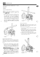
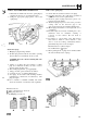
Assemble the contact breaker spring insulating
bushes and electrical leads, as illustrated,
in
the
following sequence:
(a) lower bush
(b) spring
(c)
low tension lead
(d) capacitor lead
(e) top bush
and secure with the anchor spring nut.
cam lubrication pad.
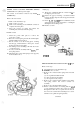
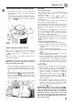
8.
Apply a few drops of engine oil to the distributor
Sliding contact
type
RR090
3,lO-
3
Adjust points
-
both
types
9.
Turn the engine in the direction of rotation until
the contacts are fully open or the heel of the
contact set is on the highest point of the cam.
10. Using a feeler gauge and the dwell angle adjuster
on the side
of
the distributor, set the points to a
nominal gap of
0,35
to
0,40
mm
(0.014
to
0.016
in).
11.
At
the earliest opportunity check and adjust the
dwell angle
-
see data
-
using spccial turning
equipment.
12.
Fit the rotor arm and distributor cap ensuring that
the
H.T.
pick
-
up brush moves freely.
I
--
*.
1
L
..
-..
0
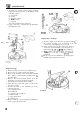
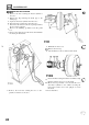
1.
Release the clips and remove the distributor cap.
2.
Remove the rotor arm from the cam spindle.
3.
Remove the retaining screw and washers and lift
the complete contact breaker assembly from
the
moveable plate.
4.
Remove
the
nut and plastic bushes from the
terminal post
to
release the leads and spring.
5.
Discard
the
old contact breaker assembly.
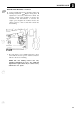
6.
Clean the new points with petrol
to
remove the
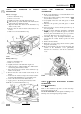
7.
Connect the leads to the terminal post in the
protective coating.
following sequence:
(b)
red lead tab
(c) contact breaker spring eye
(d) black lead tab
(e) upper plastic bush
(f)
retaining nut.
the two pegs locate in the holes.
(a) lower plastic bush
ST1083M
8.
Fit
the contact set to the moving plate ensuring that
1s