
Operating instructions


42
10 Appendix
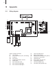
10.1 Wiring diagram
B1/B2 Ionisation electrodes
B3 Level switch
F1 Fuse control board (1.25 A, slow acting)
M1 4-stepfan
M2 Drum motor
P1 Potentiometer display contrast
S1 Safetyswitch
S3 Micro switch side cover
S4 Micro switch air intake grill 1
S5 Micro switch air intake grill 2
U1 Internal humidity sensor
U2 Radio receiver (option)
U3 Externalradiohumiditysensor(option)
T1 Transformercontrolboard
T2 Transformerfan
X5 Errorcontact,max.250VAC
X9 Programminginterface
Y1 Inlet valve (PH28A only)
Y2 Inletsafetyvalve(PH28Aonly)
PH28
X14
X15
X17
+5V
4
3
2
1
U1
P1
T1
B3
B1 B2
X5
F1
T2
M2
X9
X9
7 1
X10
2 1
1
+24V
X12
2 1
X6 X5
1 2 1 2 3
+24V
X13
5 4 3 2 1
+24V
+24V
X1
L1
L
N
PE
X3
1
2
3
5
4
X16
1
1
10
St. 1 (ws)
St. 2 (rt)
St. 3 (gu)
C2 (bn)
St. 4 (sw)
N (bl)
PE
PE
PE (gn/ge)
X4
1
2
3
5
6
4
7
8
9
10
1.25 AT
S1
C1 (ge)
P (bl)
N (sw)
PE (gn/ge)
L1 L1
L
N
PE
L
N
115 VAC
122 V
146 V
172 V
230 V
230 VAC
PE
M
Y1
Y2
Steuerprint PH27
300000642.000
Index XX
Art.Nr. XXXXXXX
U3
U2
X21
S3
X22
S4
X23
S5
Keypad&LED
Display
M