
Full Product Manual

Use and Care Guide
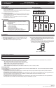
DAYLIGHT ADJUSTING INDOOR DIGITAL TIMER
Item #1002-229-532
Model #32648
UPC #030878326483
2 HOMEDEPOT.com
Please contact 1-844-871-8796 for further assistance.
Please reference page 1 to identify the right installation method for your timer and basic wiring terms.
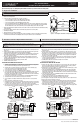
1
Single-Pole Installation
WARNING: If you are unsure or unclear about this installation, or if the wires in your box do not match the manual (not all switch boxes have
neutral wires), contact a qualied, licensed electician.
Disconnect the power at the circuit breaker or fuse box.
a. Remove the existing switch.
b. Connect the timer to the wall box wires as shown. See Figure 2.
□ Connect the hot/live Line wire to the LINE terminal of the timer.
□ Connect the hot/live Load wire to the LOAD terminal of the timer.
□ Connect the Ground wire to the GROUND terminal of the timer.
□ Connect the white Neutral wire to the NEUTRAL terminal of the timer. Often the Neutral wire can be found in
the back of the wire box connected with a wire nut. There may be several neutral wires bound together. Add
the timer Neutral wire to the other neutral wires, bound together making sure the wire nut is tight.
c. Ensure that all terminals are tightened to between 8.85 and 12.39 lbf-in., and tuck the wires into the wall box, leaving
room for the timer.
d. Use the screws (BB) to mount the timer to the wall box, being careful not to crush any wires.
e. Reinstall your wall plate.
f. Turn the main power on at the circuit breaker.
g. If the timer does not turn on, disconnect the power at the circuit breaker or fuse box. Swap the Line and Load wires
on the timer. Remount the timer and wall plate, then restore power at the fuse box or circuit breaker.
TIMER
WALL BOX
Line
TRAVELER
LOADLINE
NEUTRAL
Neutral
Load
Ground
Figure 2 - Connecting the Timer Wires for Single-Pole Installation
2
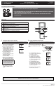
Timer On Load Side 3-Way Installation Instruction
3
Timer On Line Side 3-Way Installation Instruction
SEE FIGURES 3 & 4 BELOW
NOTE: The common is typically a dark colored screw on a single pole or 3-way toggle switch.
NOTE: If you are using your timer to control a uorescent lamp, the timer must be installed on a load-side
wiring box.
PREPARING THE SWITCH ON THE LINE SIDE
a. Disconnect the power from the circuit by turning off the circuit breaker or removing the fuse from
the fuse box.
b. Using the Line Side of Figure 3 as a visual reference, label and remove the Line wire (1) from the
common terminal (C) and the Traveler-2 wire (7) from the HOT terminal (H).
c. Using Figure 4 as a visual reference, connect the jumper wire (6) (supplied part CC), the Line wire
(1) from the common terminal (C), and the Traveler-2 wire (7) together. You should have three
wires connected with one wire nut.
d. Connect the other end of the jumper wire (6) back to the common terminal (C) on the switch.
Consider recording the marking/color coding of the Traveler-1 (5) and Traveler-2 (7) wires so you
can tell them apart for later use.
e. Carefully tuck the wires into the box, leaving room for the switch.
f. Install the switch back into the box.
INSTALLING THE TIMER ON THE LOAD SIDE
a. Using the Load Side of Figure 3 as a visual reference, remove the Load Side 3-way switch
and the four wires, labeling the wire removed from the common terminal as Load (4) and the
wires from the HOT terminals (H) as Traveler-1 (5) and Traveler-2 (7).
b. Using the Timer On Load Side of Figure 4 as a visual reference for the remaining steps,
connect the Load wire (4) to the LOAD terminal of the timer.
c. Connect the Traveler-2 wire (7) to LINE terminal of the timer.
d. Connect the Traveler-1 wire (5) to the TRAVELER terminal of the timer.
e. Connect the white Neutral wire (2) from the switch box to the NEUTRAL terminal of the timer.
More neutral wires may be bundled in the back of the switch box; there may be several
neutral wires bound together with a wire nut. Add the Neutral wire to the other neutral wires
bound together, ensuring the wire nut is tight.
f. Connect the green Ground wire (3) in the switch box to the GROUND terminal of the timer.
g. Carefully tuck the wires into the switch box, leaving room for the timer.
h. Use the supplied screws (BB) to install the timer, being careful not to crush or pinch the
wires.
i. Restore power at the circuit breaker or fuse box.
j. Verify that the load turns on/off when you manually turn the timer ON and OFF. Perform this
test with the remote switch in both positions. You should hear the timer relay click on/off. If
you hear the relay click but the load does not turn on/off properly, check your wiring.
k. If the load does not operate properly, disconnect the power at the circuit breaker or fuse box.
Then swap the Traveler-2 (Line) wire (7) and Traveler-1 wire (5) on the timer.
TRAVELER
LOADLINE
NEUTRAL
Figure 3 - Typical Wiring
Schematic for 3-Way Installation
2
7
5
6
1
3
Ground
C
Typical Wiring Diagram for 3-way installation
with timer on load side
Load
Line
5
1
7
3
3
Hot Side
Line
Ground
LINE SIDE
SWITCH ON LINE SIDE
LOAD SIDE
TIMER ON LOAD SIDE
C
HH
5
4
7
C
HH
Figure 4 - Connecting the Timer Wires for a
3-Way Installation - Timer on Load Side
Load
1 = Line
2 = Neutral
3 = Ground
4 = Load
5 = Traveler-1
6 = Jumper
*7 = Traveler-2
C = Common
terminal
In a typical 3-way application there are two 3-way switches. The switch on the “HOT”
side has the common terminal tied to 120VAC. The switch on the “LOAD” side has the
common terminal tied to the load that the switches turn on and off.
Load
Neutral
Traveler-2 (Line)
Ground
Traveler-1
5
3
7
4
2
*Traveler-2 (7) carries Line to the timer
HH
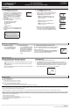
SEE FIGURES 5 & 6 BELOW
NOTE: The common is typically a dark colored screw on a single pole or 3-way toggle switch.
NOTE: If you are using your timer to control a uorescent lamp, the timer must be installed on a load-side wiring
box.
PREPARING THE SWITCH ON THE LOAD SIDE
a. Disconnect the power from the circuit by turning off the circuit breaker or removing the fuse
from the fuse box.
b. Using the Switch On Load Side of Figure 5 as a visual reference, label and remove the Load
wire (4) from the common terminal (C) and the Traveler-2 wire (7) from the HOT terminal (H).
c. Using Figure 6 as a visual reference, connect the jumper wire (6) (supplied part CC), the Load
wire (4) from the common terminal (C), and the Traveler-2 wire (7) together. You should have
three wires connected with one wire nut.
d. Connect the other end of the jumper wire (6) back to the common terminal (C) on the switch.
Consider recording the marking/color coding of the Traveler-1 (5) and Traveler-2 (7) wires so
you can tell them apart for later use.
e. Carefully tuck the wires into the switch box leaving room for the timer.
f. Install the switch back into the box.
INSTALLING THE TIMER ON THE LINE SIDE
a. Using the Line Side of Figure 5 as a visual reference, remove the Line Side 3-way switch and
the four wires, labeling the wire removed from the common terminal (C) as Line (1) and the
wires from the HOT terminals (H) as Traveler-1 (5) and Traveler-2 (7).
b. Using the Timer on Line Side of Figure 6 as a visual reference for the remaining steps, connect
the Line wire (1) to the LINE terminal of the timer.
c. Connect the white Neutral wire (2) to the NEUTRAL terminal of the timer. More neutral wires
may be bundled together in the back of the switch box; there may be several neutral wires
bound together with a wire nut. Add the Neutral wire to the other neutral wires bound together,
ensuring the wire nut is tight.
d. Connect the Traveler-1 wire (5) to the TRAVELER terminal of the timer and the Traveler-2 wire
(7) to the LOAD terminal of the timer.
e. Connect the green Ground wire (3) to the GROUND terminal of the timer.
f. Carefully tuck the wires into the switch box, leaving room for the timer.
g. Use the supplied screws (BB) to install the timer, being careful not to crush or pinch the wires.
h. Restore power at the circuit breaker or fuse box.
i. Verify that the load turns on/off when you manually turn the timer ON and OFF. Perform this
test with the remote switch in both positions. You should hear the timer relay click on/off. If
you hear the relay click but the load does not turn on/off properly, check your wiring.
j. If the load does not operate properly, disconnect the power at the circuit breaker or fuse box.
Then swap the Traveler-2 (Load) wire (7) and Traveler-1 wire (5) at the timer or the toggle switch.
TRAVELER
LOADLINE
NEUTRAL
Typical Wiring Diagram for a 3-way installation
with timer on line side
Figure 6 - Connecting the Timer Wires for a 3-Way
Installation - Timer on Line Side
1 = Line
2 = Neutral
3 = Ground
4 = Load
5 = Traveler-1
6 = Jumper
*7 = Traveler-2
C = Common
terminal
2
7
5
6
3
Ground
SWITCH ON LOAD SIDE
4
Load
C
Figure 5 - Typical Wiring
Schematic for 3-Way Installation
5
1
7
Hot Side
Line
LINE SIDE LOAD SIDE
C
HH
5
4
7
C
HH
Load
In a typical 3-way application there are two 3-way switches. The switch on the “HOT”
side has the common terminal tied to 120VAC. The switch on the “LOAD” side has the
common terminal tied to the load that the switches turn off and on.
Line
Neutral
Traveler-2 (Load)
Ground
Traveler-1
5
3
7
1
2
TIMER ON LINE SIDE
3
3
Ground
*Traveler-2 (7) carries Load
to the 3-way switch
H H