
Installation Guide


TEMPLATE
NOTE: Double check your product for
the correct hole sizes.
1-3/4”
(45 mm)
1-3/8”
(35 mm)
1-9/16”
(40 mm)
2”
(51 mm)
Ø 2-1/8” (54 mm)
2-3/4” (70 mm)
2-3/8” (60 mm)
Drill a 1” (25 mm) diameter
hole at the center of the door
edge.
Fold here.
Place on the door edge.
Backset
Backset
1-3/4”
(45 mm)
1-3/8”
(35 mm)
1-9/16”
(40 mm)
2”
(51 mm)
Ø 1-1/2” (38 mm)
2-3/4” (70 mm)
2-3/8” (60 mm)
Drill a 1” (25 mm) diameter
hole at the center of the door
edge.
Fold here.
Place on the door edge.
Backset
Backset
OR
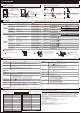
WARRANTY
CAUTION:
Please use four alkaline batteries for the best performance.
CARE and MAINTENANCE:
The following instructions should be followed to properly protect and maintain your lockset:
Read the precautions and instructions in this manual before installing and using this lock. Save this manual for future reference.
A. Remove locks, or do not install locks, prior to painting your door.
B. Periodically clean with mild soap and a soft cloth only.
C. Do not use any abrasives or chemical products containing alcohol, benzene, acids, and avoid using sharp or abrasive objects to clean this lockset.
D. Do not allow any water or liquids into the lockset during installation.
A. Do not attempt to disassemble any internal components of the lockset. Doing so will void the limited warranty.
B. Do not drop or hit the lockset. Too much shock may result in permanent damage.
C. Do not use pins or sharp objects to press the keypad.
D. Always create a backup of information you wish to keep (programming code, user codes,etc.) Please use the last page of this booklet as a reference.
E. Promptly change the Master Code before operating this lockset
Safety Information
WARNING:
If the door needs to be drilled, please be familiar with how to use a drill safely and understand all of the door preparation steps before proceeding.
2
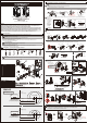
1
Pre-installation – Tools Required / Hardware Included
4
Installation
3
1
Cut out TEMPLATE (reverse page) and use to mark the door, drill holes, and chisel out the mortise.
NOTE: Drill from both sides of the door to prevent wood splitting.
Pre-installation (continued) – Door Preparation
1"
(25 mm)
2-1/8"(54 mm)
1-1/2"(38 mm)
or
Backset
Centerline
2-1/8"(54 mm)
1-1/2"(38 mm)
or
Note: For drive-in latch.
Simply insert latch.
1”
(25 mm)
Outline
Chisel 5/32” deep
Faceplate
NOTE: If your door is pre-drilled, check the hole sizes to make sure they are the proper size. If they are the proper size, skip to the INSTALLATION section.
c
b
f
e
a
d
Dust box
Strike plate
CC
Prepare the door jamb – use the strike plate as a template to drill the latch and screw holes and chisel out the mortise. The strike plate must fit flush with the surface
of the door jamb.
2
Door jamb hole dimension
Strike dimentions
b. 1-9/64"(29 mm)
d. 5/32"(4 mm)
e. 2-1/4"(57 mm)
f. 1"(25 mm)
a. 1-3/16"(30 mm)
c. 7/8"(22 mm)
A. Attach the correct faceplate
B. Set the latch backset length
1
INSTALLING THE LATCH
Edge of door
The cable must be arranged as shown in the diagram.
Insert screws
and tighten.
Connect the cable firmly into connector port .
The bulged part of the mounting plate
must face towards the door.
B. Install the lock assemblies
Slide the cable through the
notch in mounting plate.
INSTALLING THE LOCK ASSEMBLIES
2
The latch bolt should be
in retracted position.
Thread the cable through
the hole and under the latch.
A. Door bore options
BB
LIMITED LIFETIME MECHANICAL AND 1 YEAR ELECTRONIC WARRANTY
The retailer of this product, hereby warrants, subject to the conditions set forth below, that it will either repair or replace, at its option, this product if it
proves to be defective by reason of improper workmanship or materials within the original purchaser's limited time. In order to obtain repairs or
replacement under this limited warranty you must bring this product to the retailer's store in which you bought it.
Original purchaser: This limited warranty is limited to the original purchaser at retail of this product from retailer.
Except to the extent prohibited by applicable law, no other warranties, whether express or implied, including the warranties of merchantability and fitness
for a particular purpose, shall apply to this product. Under no circumstances shall retailer be liable for consequential or incidental damages in connection
with this product. To the extent retailer is prohibited by applicable law from excluding implied warranties, the duration of such implied warranties which
are not excludable shall be the original purchaser's lifetime. Some states do not allow the limitation on how long an implied warranty lasts, so the above
limitation on the duration of implied warranties which are not excludable, if any, may not apply to you. Some states do not allow the exclusion or limitation
of incidental or consequential damages, so the above limitation or exclusion of incidental or consequential damages may not apply to you.
Retailer neither assumes not authorizes any representative or other person to assume for it any obligation or liability other than such as is expressly set
forth herein. This limited warranty gives you specific legal rights, and you may also have other rights which vary from state to state.
Package Contents
22" (52 mm) Mounting Bolt
2
BB 3/4" (19 mm) Screw
4
CC 3/4" (19 mm) Latch screws
1
DD 1-1/4" (32 mm) Screw
Part
Description
Quantity
AA
DD
BB
CC
FOR
G32-TPD0012-A9-XQ Rev. 18/07-02
OR
Faceplate
Edge of door
Drive-in
collar
Flat head screwdriver
C. Install the latch
OR
Backset
CC
Wood block (not included)
Drive-in latch
Tap latch flush
CC
Hardware Used
Actual Size
AA
Actual Size
Hardware Used
DD
Actual Size
Actual Size
BB
Hardware Used
Questions, problems, missing parts? Before returning to the store,
call Defiant Customer Service
TOLL FREE HELP LINE 1-877-ONE-LOCK
HOMEDEPOT.COM
08:30 a.m.-05:30 p.m., EST, Monday - Friday
CC
Hardware Used
Actual Size
Your latch is set for 2-3/8” backset. It can be adjusted if needed to 2-3/4” (skip this if your door has a 2-3/8” backset).
Optional Optional Optional Optional
Optional
Optional
AA
AA
AA
AA
Install batteries
Install battery cover
CAUTION :
1.Please use four alkaline batteries for better performance. Be sure to insert them correctly by matching the + and – polarity
markings. Do not mix old batteries and new batteries or standard (carbon-zinc) with alkaline batteries.
2.Install and test lock with door OPENED to avoid being locked out.
For 2-3/8” backset: 3-7/16”
For 2-3/4” backset: 3-13/16”
Depth of latch hole
a
2
8
3
2
8
3
2
-
3
/
8
”
(
6
0
m
m
)
b
180º
2
8
3
2
8
3
2
4
3
2
4
3
c
2
-
3
/
4
”
(
7
0
m
m
)
Note : The metal connector
side should face outward.
WRONGCORRECT
Remove the Battery Cover
Press
Do NOT leave the key in
the cylinder during
installation
I Dust Box
J Key
K Drive-in Collar (Optional)
L Exterior Gasket
E Interior Assembly 1
F Battery Cover 1
G Latch 1
H Strike Plate 1
2
1
1
1
A Exterior Assembly
B Power Cable
C Torque blade
D Mounting Plate
1
1
Part
Description
Quantity
1
1
B
H
CC
AA
BB
C
B
J
A
L
G
D
E
F
K
I
DD
AA
DD
Optional
AA
adapter collar
screw
post
Ø 1-1/2”
(38 mm)
If your door has a 1-1/2”(38mm)
bore hole, remove the screw
post and the adapter collar before
installation.
Enter default Master Code(
12345678
).
Wait until Green LED lights up to complete
bolt direction setup.
OR