
Instructions / Assembly

THANK YOU
We appreciate the trust and con dence you have placed in De ant through the purchase of
this indoor auto shut off spring-wound timer. We strive to continually create quality products
designed to enhance your home. Visit us online to see our full line of products available for
your home improvement needs. Thank you for choosing De ant!
USE AND CARE GUIDE
INDOOR AUTO SHUT OFF SPRING-WOUND TIMER
OFF
60
50
10
TURN
PAST
5
20
40
Safety Information
This timer ts in any standard 2-1/2 in. deep wall box. The timer ts both toggle and rocker/
decorator wall plates in a single or multi-gang vertically installed wire box. If you are unsure
about the installation of this timer please contact a licensed electrician.
WARNING: RISK OF ELECTRIC SHOCK.
□ Installation by a licensed electrician is recommended.
□ Installation and use of this equipment should be in accordance with
provisions of the U.S. national electrical code, applicable local codes
and pertinent industry standards.
□ Shut off power at the fuse box or circuit breaker before installation.
□ Do not use in wet locations.
□ For indoor use only unless installed in a NEMA Type 3R enclosure.
WARNING: RISK OF FIRE.
□ Only use copper wire with this device.
□ Do not use to control a receptacle.
□ Do not exceed electrical ratings.
□ Do not use to control appliances with heating elements (cooking
appliances, heaters, irons, etc.)
Specifi cations
125 Vac, 50/60 Hz, 20 A Res./Gen., 7 A Tungsten, 1 HP
250 Vac, 50/60 Hz, 10 A Res./Gen., 2 HP
277 Vac, 50/60 Hz, 10 A Res./Gen.
Pre-Installation
HARDWARE INCLUDED
A
A - Wire Nut x 1 BB - Screw x 2 CC - Plate screw x 2
DD - Light almond faceplate x 1 EE - Knob x 1
OFF
60
50
10
TURN
PAST
5
20
40
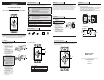
Product Description
OFF
60
50
10
TURN
PAST
5
20
40
C
A
B
Part Description
A Interchangeable knob (in white and almond)
B Nut (located underneath the knob (A))
C Interchangeable faceplate (in white and almond)
Warranty
1 YEAR WARRANTY
The manufacturer guarantees this product to be free of defects in materials and
workmanship for 1 year from the date of purchase. If this product is defective, call 866-308-
3976 for repair or replacement parts or return the product to the store from which it was
purchased. This guarantee does not include normal wear and tear, LEDs, or batteries.
Contact the Customer Service Team at 1-866-308-3976 or visit www.HomeDepot.com.
Questions, problems, missing parts? Before returning to the store,
call De ant Customer Service
8 a.m.-6 p.m., EST, Monday-Friday
1-866-308-3976
HOMEDEPOT.COM
Item# 0000000000
Installation
1
Preparing the timer for
installation
WARNING: Turn the power off at
the circuit breaker or fuse box before
installation.
Remove the existing wall plate
and switch from your vertically-
installed wall box.
Strip wires to 5/16 in. long.
Remove the timer from the
package and carefully remove the
knob (A), nut (B), and faceplate (C)
from the timer.
Loosen the LINE1 (1) and LOAD1 (2)
screws with a athead or Phillips
head screwdriver to open the
wall plate where the wires will be
secured on the side of the timer.
LOAD 2
LINE 1
TOP
LINE 2
LOAD 1
1
0
5
T
U
R
N
PAST
2
0
3
0
4
0
5
0
6
0
0
B
A
C
1
2
Installation
2
Connecting the wires
Strip all wires from timer 5/16".
Insert the Line side wire from the wire box into the side of the timer marked LINE1
under the wire plate and tighten the LINE1 screw (1).
Insert the Load side wire from the wire box into the side of the timer marked
LOAD1 under the wire plate and tighten the LOAD1 screw (2).
Attach the bare ground wire (3) from the timer to the bare ground wire in the wire
box and secure together using the wire nut (AA).
LOAD 2
LINE 1
TOP
LINE 2
LOAD 1
1
2 3
AA
Line
Load
Ground
Black
Black
Black
Light
WhiteWhite
= Wiring Nut
SPST Wiring Example
120 / 277 VAC
Power Source
Spring Wound Timer
Load 1
Line 1
C
No
Installation
3
Attaching the timer to the
wall box
Insert the timer into the 2-1/2 in.
wall box being careful not to pinch
any wires. Ensure the word TOP
located on the front of the timer
is facing up.
Fasten the timer to the wall box
using the screws (BB).
Place a standard toggle or rocker/
decorator wall plate (not included)
on the timer and attach using the
wall plate screws (CC). Be careful
not to overtighten as this could
damage your wall plate.
NOTE: When using a toggle wall
plate, the two wall plate screws are
not required in order to secure the wall
plate. The nut (B) will hold the wall plate
in position once assembled. If screws
are required for the toggle wall plate
they must be self-tapped into the timer
by carefully applying inward pressure
while turning the screw in order to self-
tap into the timer. If using the rocker/
decorator style wall plate, screw the
wall plate into the top and bottom tabs
of the timer using the screws supplied
with your current wall plate. DO NOT
OVERTIGHTEN.
Slide the timer dial plate (C)
over the knob extension of the
timer. It should t snugly onto the
wall plate. Be sure the “OFF” is
oriented with the TOP of the timer
as marked on the timer. Carefully
screw on the nut (B).
Push the timer knob (A) onto the
knob extension. Be sure the pointer
is lined up with “OFF” on the dial
plate (C).
Turn the power on at the circuit
breaker or fuse box.
10
TURN
PAST
MINUTES
20
30
40
50
60
0
Wire
Terminal
2½” min
B
A
BB
CC
C
10
TURN
P
AST
MINUTES
20
30
40
5
0
60
0
Wire
Terminal
2½” min
B
A
BB
CC
C
Operating Instructions
Turn the knob (A) clockwise to the desired time period. The timer will automatically
turn the current off at the end of the time period indicated on the timer. Make sure to
turn past the 5 minute marker.
A
OFF
60
50
10
TURN
PAST
5
20
40